Fuel cell system

a fuel cell and system technology, applied in the field of fuel cell systems, can solve the problems of difficult to make the whole system down-sized and compact, deteriorating energy efficiency of the whole system, etc., and achieve the effect of reducing parasitic power needed, down-sized and compa

Inactive Publication Date: 2010-07-20
SAMSUNG SDI CO LTD
View PDF21 Cites 2 Cited by
  • Summary
  • Abstract
  • Description
  • Claims
  • Application Information

AI Technical Summary

Benefits of technology

[0010]An embodiment of the present invention provides a fuel cell system that contains a supplier for providing both fuel and air, thereby reducing parasitic power needed for driving the system and rendering the entire system down-sized and compact.
[0014]In the fuel cell system according to the present invention, the reaction source supplier can further contain a reformer adapted to connect to the storage region and to generate hydrogen gas from the fuel through a chemical catalytic endothermic reaction and to supply the hydrogen gas to the electricity generating element.

Problems solved by technology

Since parasite powers are increased for driving such pumps, energy efficiency of the whole system is deteriorated.
The prior fuel cell system also needs space for equipping such pumps and so it is difficult to make the whole system down-sized and compact.

Method used


Image

  • Fuel cell system
  • Fuel cell system
  • Fuel cell system

Examples


Embodiment Construction

[0027]An embodiment of the present invention will hereinafter be described in detail with reference to the accompanying drawings. However, the present invention can have various modifications and equivalent arrangements and it is to be understood that the invention is not limited to the described embodiments.

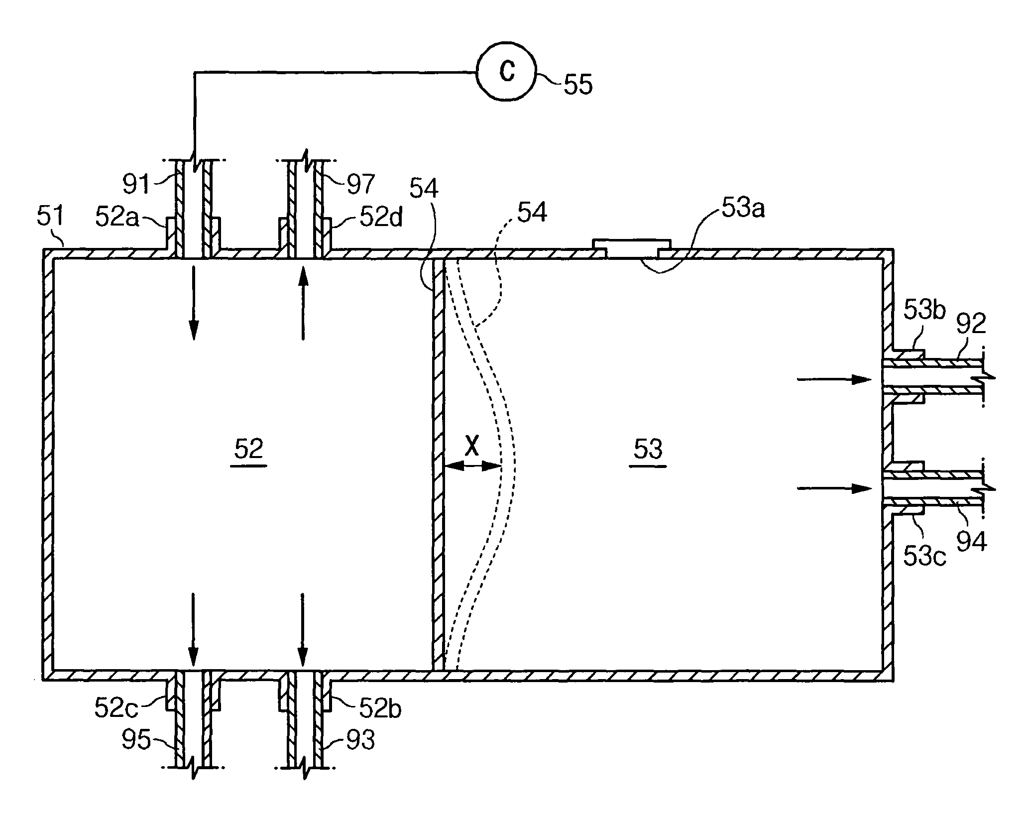
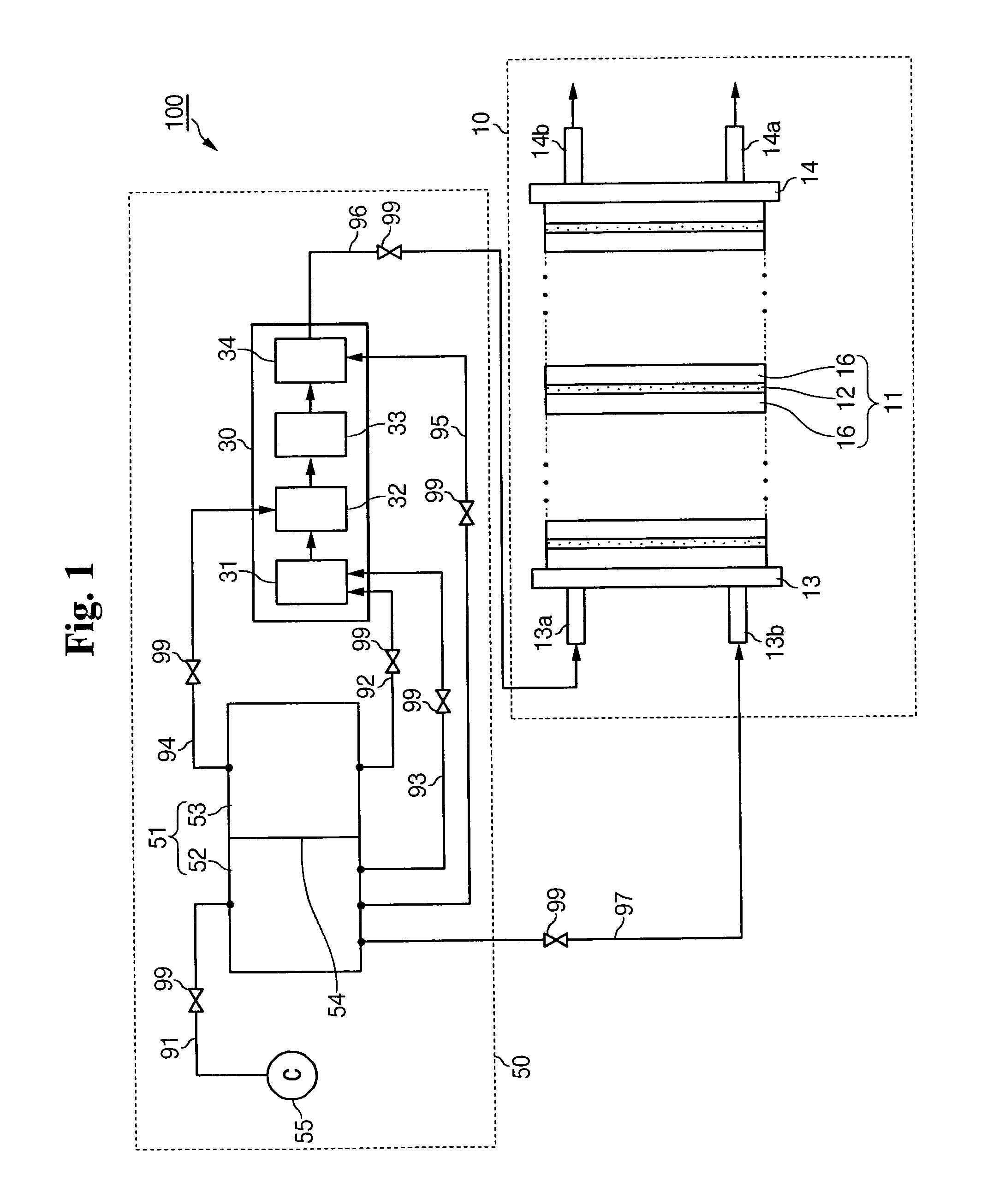
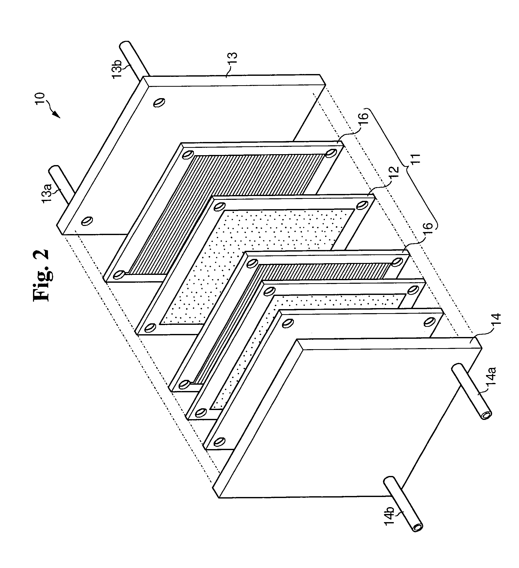
[0028]FIG. 1 is a schematic diagram of an entire structure of a fuel cell system according to one embodiment of the present invention and FIG. 2 is an exploded perspective view of the stack structure of FIG. 1.

[0029]According to the embodiment of the present invention with reference to the drawings, a fuel cell system 100 uses a Polymer Electrolyte Membrane Fuel Cell (PEMFC), which generates hydrogen gas by reforming a hydrogen-containing fuel and then electricity by electrochemically reacting the hydrogen and oxidizing agent.

[0030]A fuel used to generate electricity in the fuel cell system 100 can be any type of fuels such as methanol, ethanol, or natural gas, and the like whet...


PUM

PropertyMeasurementUnit
electrical energyaaaaaaaaaa
pressureaaaaaaaaaa
heat energyaaaaaaaaaa

Abstract

A fuel cell system includes at least one electricity generating element to generate electrical energy through an electrochemical reaction of hydrogen and oxygen, and a reaction source supplier adapted to connect to the electricity generating element and to provide a hydrogen-containing fuel and oxygen-containing air to the electricity generating element. The reaction source supplier includes a first divided region for storing compressed air, a second divided region for storing the fuel, and a storage region having an elastic partition adapted to divide the adjacent first and second divided regions.

Description

CLAIM OF PRIORITY[0001]This application makes reference to, incorporates the same herein, and claims all benefits accruing under 35 U.S.C. §119 from an application for FUEL CELL SYSTEM AND FUEL SUPPLY APPARATUS earlier filed in the Korean Intellectual Property Office on 7 Sep. 2004 and there duly assigned Serial No. 10-2004-0071155.BACKGROUND OF THE INVENTION[0002]1. Field of the Invention[0003]The present invention relates to a fuel cell system. More particularly, the present invention relates to a fuel cell system including a reaction source supplier to provide hydrogen along with an oxidant.[0004]2. Description of the Related Art[0005]A fuel cell is a power generation system for producing electrical energy through the electrochemical redox reaction of oxygen and a fuel, such as hydrogen or a hydrocarbon-based material such as methanol, ethanol, natural gas, or the like.[0006]A fuel cell can be classified into a phosphoric acid type, a molten carbonate type, a solid oxide type, a ...

Claims


Application Information

Patent Timeline
Patent Type & Authority Patents(United States)
IPC IPC(8): H01M2/00H01M8/18
CPCH01M8/04089H01M8/04208H01M8/0662H01M8/1002H01M8/1009Y02E60/521H01M8/1007Y02E60/50H01M8/04H01M8/06
Inventor KIM, JU-YONGLIM, HYUN-JEONGHAN, JI-SEONG
Owner SAMSUNG SDI CO LTD
Why Eureka
Try Eureka