
Tuning fork type piezoelectric resonator having a node of common mode vibration in constructed part of base

a technology of piezoelectric resonators and common mode vibration, which is applied in the direction of generators/motors, instruments, and device material selection, etc., can solve the problems of deterioration of frequency characteristics, insufficient stability of resonator elements, and inability to stand practical use of resonator elements, etc., to achieve stability and stability. characteristics

Inactive Publication Date: 2010-07-20
SEIKO EPSON CORP
View PDF12 Cites 11 Cited by
  • Summary
  • Abstract
  • Description
  • Claims
  • Application Information

AI Technical Summary

Benefits of technology

The invention provides a tuning fork type piezoelectric resonator element and a tuning fork type piezoelectric resonator with stable characteristics. The resonator element has a constricted part located between a pair of cuts, which results in a decrease in the inherent resonance frequency of the common mode and stabilizes the characteristics. The inherent resonance frequency of the common mode is separated from the inherent resonance frequency of the fundamental mode. The tuning fork type piezoelectric resonator also includes a package housing the resonator element and a connecting member connecting the resonator element to the package, with a dynamic storage elastic modulus or a Young modulus of the connecting member being 100 MPa or more.

Problems solved by technology

However, the cuts 906 alone are not sufficient to stabilize the characteristics of a tuning fork type resonator element.
In particular, if the tuning fork type piezoelectric resonator element is connected using a connecting member having an apparent elastic modulus, a dynamic storage elastic modulus, or a Young modulus during operation of 100 MPa or more, the frequency characteristics notably deteriorate and the resonator element does not stand practical use.
As a result, the vibrations of the X common mode and the fundamental mode are combined, leading to deterioration of the characteristics.
As a result, the vibration of the common mode may not be readily generated when excited in the fundamental mode, and the characteristics may be stabilized.

Method used


Image

  • Tuning fork type piezoelectric resonator having a node of common mode vibration in constructed part of base
  • Tuning fork type piezoelectric resonator having a node of common mode vibration in constructed part of base
  • Tuning fork type piezoelectric resonator having a node of common mode vibration in constructed part of base

Examples


Embodiment Construction

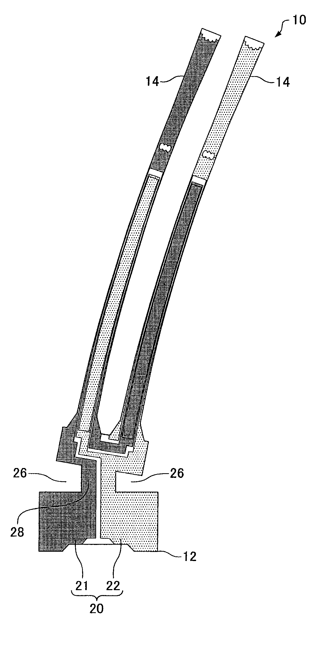
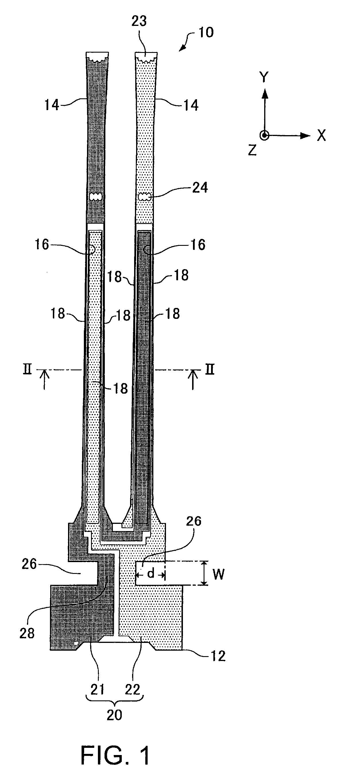
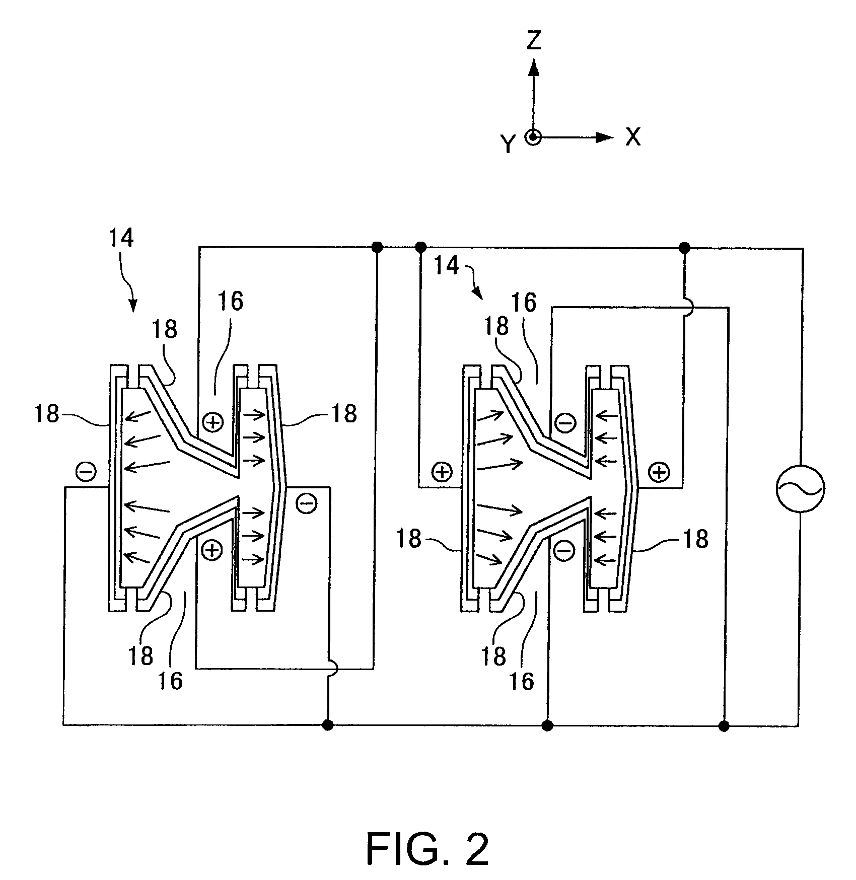
[0021]FIG. 1 is a plan diagram showing a tuning fork type piezoelectric resonator element according to one embodiment of the invention. FIG. 2 is an enlarged sectional diagram of the tuning fork type piezoelectric resonator element of FIG. 1, taken on a line II-II. A bottom surface of the resonator element of FIG. 1 shows symmetry, as does the plan diagram. A tuning fork type piezoelectric resonator element 10, which is made of quartz crystal, has front and rear surfaces which face opposite from each other and define the thickness of the resonator arms. The tuning fork type piezoelectric resonator element 10 includes a base 12 and a pair of resonator arms 14 independently extending from the base 12. In addition to the resonator arms 14, the base 12 may also have support arms not shown in the drawings.

[0022]The resonator arms 14 includes: the front and rear surfaces facing opposite from each other and defining the thickness of the arms 14, and side surfaces connecting the front and r...


PUM


Abstract

A tuning fork type piezoelectric resonator element includes: a base including a pair of cuts provided opposite from each other and a constricted part located between the pair of cuts, a pair of resonator arms extending from the base, and an excitation electrode provided to each of the pair of resonator arms. When the pair of resonator arms vibrate at an inherent resonance frequency fcom of a common mode at which the pair of resonator arms swing in a same direction, a node of the vibration of the common mode is located at the constricted part.

Description

BACKGROUND[0001]1. Technical Field[0002]The present invention relates to a tuning fork type piezoelectric resonator element and a tuning fork type piezoelectric resonator.[0003]2. Related Art[0004]It is known that leak of vibration from resonator arms 902 is reduced if a base 904 having the resonator arms 902 extended therefrom is provided with cuts 906, with reference to FIG. 9 (see JP-A-2002-261575). However, the cuts 906 alone are not sufficient to stabilize the characteristics of a tuning fork type resonator element. For example, referring to FIG. 9, the vibration of the right and left resonator arms 902 may become irregular. In particular, if the tuning fork type piezoelectric resonator element is connected using a connecting member having an apparent elastic modulus, a dynamic storage elastic modulus, or a Young modulus during operation of 100 MPa or more, the frequency characteristics notably deteriorate and the resonator element does not stand practical use. The inventor of ...

Claims


Application Information

Patent Timeline
Patent Type & Authority Patents(United States)
IPC IPC(8): H01L41/08G01P9/04H03H9/21H01L41/09H01L41/18H01L41/22H01L41/23H01L41/313H03H9/19H03H9/215
CPCH03H9/1021H03H9/215
Inventor HIRASAWA, KAZUYA
Owner SEIKO EPSON CORP
Learn More