
Threshold voltage method and apparatus for ESD protection

a technology of esd protection and threshold voltage, applied in the direction of electrical devices, transistors, arrangements responsive to excess voltage, etc., can solve the problems of undesirable triggering destroying the entire integrated circuit, and affecting the safety of the protection clamping circui

Active Publication Date: 2010-07-20
ATMEL CORP
View PDF22 Cites 16 Cited by
  • Summary
  • Abstract
  • Description
  • Claims
  • Application Information

AI Technical Summary

Benefits of technology

This solution effectively differentiates between ESD events and power-on conditions, reducing the risk of false triggering and allowing for rapid power-on without interference, while maintaining protection against high voltage discharges.

Problems solved by technology

ESD is a serious problem for semiconductor devices since it has the potential to destroy the entire integrated circuit.
The principal difficulty for designers is to make a protection device which would be able to protect the integrated circuit without interfering with nominal chip functionality.
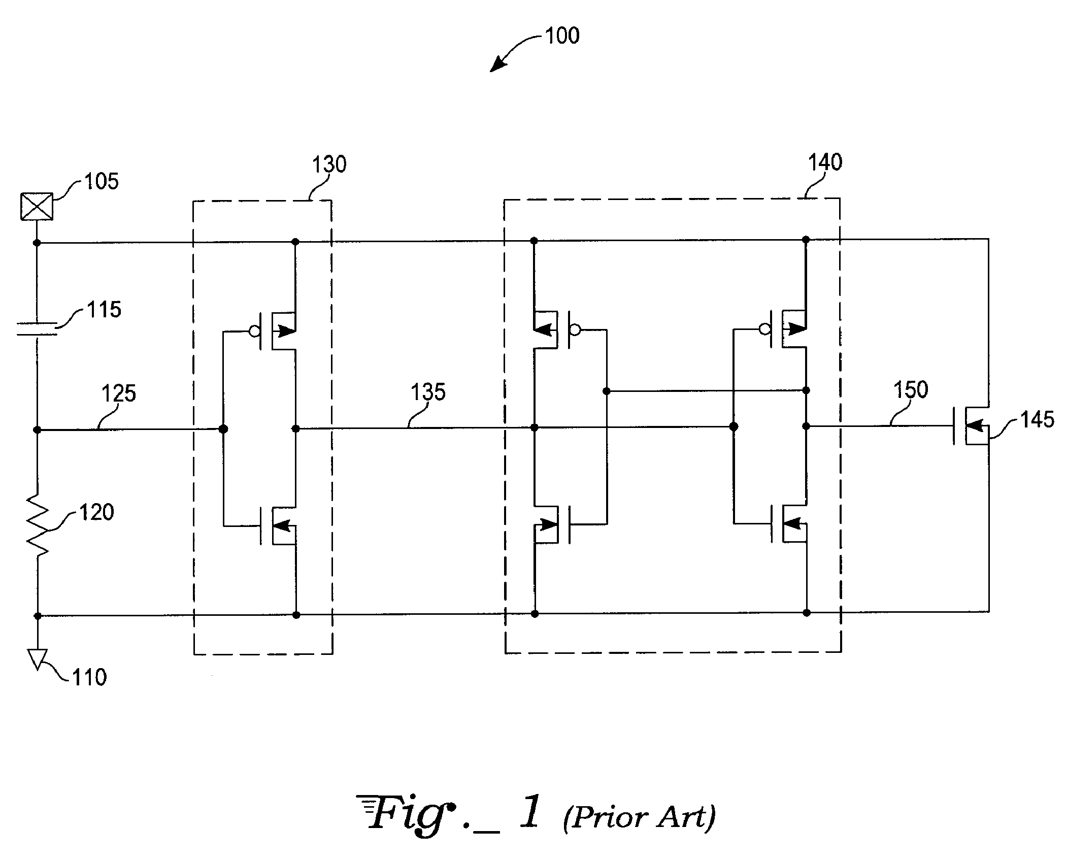
However, due to this approach to signal differentiation, rapid rise times occurring during integrated circuit power up are close to the magnitude of rise times of an ESD event.
Undesirable triggering of the protection clamping circuit may occur either due to rapid power-on conditions or during high current consumption, such as occurs with simultaneously switching outputs (SSO).
RC time constant reduction does not help in differentiating between ESD events with rise times similar to power-on events.

Method used


Image

  • Threshold voltage method and apparatus for ESD protection
  • Threshold voltage method and apparatus for ESD protection
  • Threshold voltage method and apparatus for ESD protection

Examples


Embodiment Construction

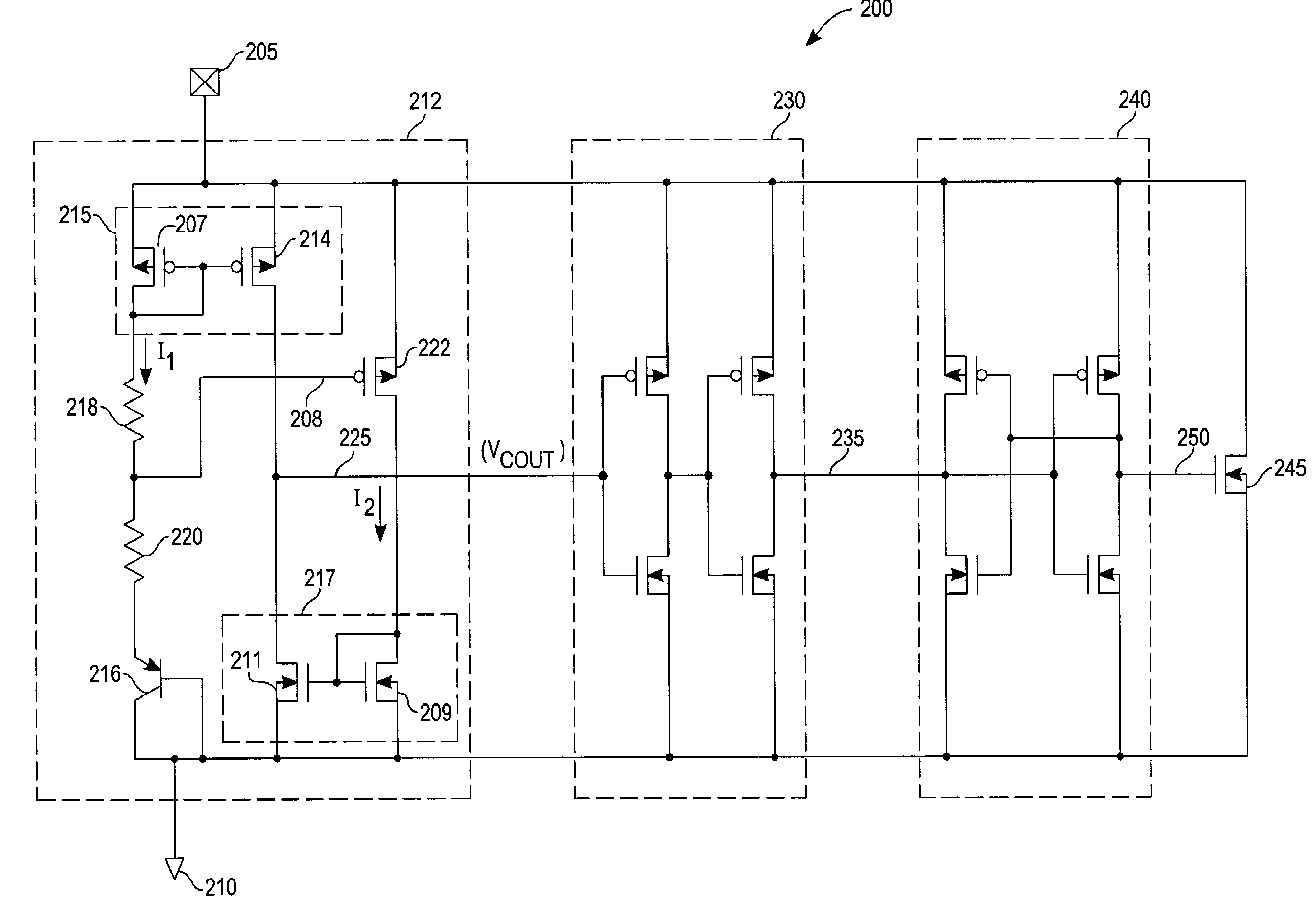
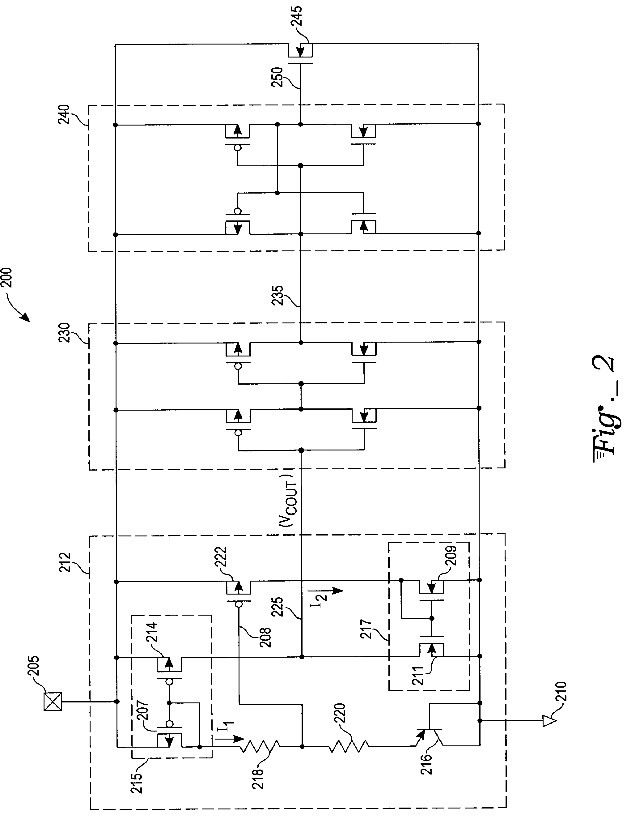
[0016]With reference to FIG. 2, a comparator 212 connects between a power supply terminal 205 and ground 210 in an exemplary ESD protection circuit 200. A buffer 230 and a latch 240 each connect between the power supply terminal 205 and ground 210. A comparator output line 225 connects between an output of the comparator 212 and an input of the buffer 230. A trigger line 235 connects between an output of the buffer 230 and an input of the latch 240. A shunt device 245 connects between the power supply terminal 205 and ground 210. A shunt trigger line 250 connects between an output of the latch 240 and an input of the shunt device 245.

[0017]The buffer 230 is, for example, a succession of two CMOS inverters in series between the comparator output line 225 and the trigger line 235. The latch 240 is, for example, a cross coupled set of CMOS inverters with a latch input at the trigger line 235 and a latch output coupled to the shut trigger line 250.

[0018]In the present exemplary embodime...


PUM


Abstract

An electrostatic discharge protection circuit comprises a comparator coupled between a power supply terminal and ground. The comparator responds to an electrostatic discharge event producing a trigger signal at a comparator output. The comparator comprises a first and second current mirror. The first and second current mirrors each comprise a sense device and a mirror device. The mirror devices are coupled in series between the power supply terminal and ground. The first mirror device produces an incident current and the second mirror device receives an absorption current. With a supply voltage on the power supply terminal equal to or greater than a trigger supply voltage, the absorption current exceeds the incident current and produces a trigger signal at the comparator output. The trigger signal activates a shunt device that shunts current from the power supply terminal to ground.

Description

TECHNICAL FIELD[0001]A present invention generally relates to electrostatic discharge protection devices for integrated circuits. More specifically, the device is activated by threshold voltage for triggering an electrostatic discharge shunting device.BACKGROUND ART[0002]It is known in the integrated circuit industry that build up of static charge may lead to development of extremely high voltage near input of an integrated circuit. Electrostatic discharge (ESD) refers to the phenomenon of an electrical discharge of high current over a short duration where the current results from a buildup of static charge on or near the integrated circuit package. ESD is a serious problem for semiconductor devices since it has the potential to destroy the entire integrated circuit. It is important to provide a full-chip method of protection against such damage. The principal difficulty for designers is to make a protection device which would be able to protect the integrated circuit without interf...

Claims


Application Information

Patent Timeline
Patent Type & Authority Patents(United States)
IPC IPC(8): H02H9/02
CPCH01L27/0285
Inventor RIVIERE, ANTOINEDEMOLLI, FREDERICBERNARD, DAVID
Owner ATMEL CORP
Learn More