
Variable gain amplifier, and AM-modulated signal reception circuit and detection circuit

a technology of ammodulated signal and amplifier, which is applied in the direction of horology, transmission monitoring, instruments, etc., can solve the problems of linearity worsening, the minimum operating supply voltage cannot be made small, and the variable gain amplifier is unsuited to low supply voltage operation such as battery drive, so as to improve the follow-up characteristic of an agc circuit, wide variable gain range, and improve linearity

Active Publication Date: 2010-07-20
SUMITOMO ELECTRIC IND LTD
View PDF11 Cites 5 Cited by
  • Summary
  • Abstract
  • Description
  • Claims
  • Application Information

AI Technical Summary

Benefits of technology

[0042]The present invention provides a variable gain amplifier which enhances a linearity and which has a wide variable gain range, an AM-modulated signal reception circuit in which the noise of an input portion is reduced to improve the follow-up characteristic of an AGC circuit, and an AM-modulated signal detection circuit which produces an output precisely corresponding to a peak-value envelope.

Problems solved by technology

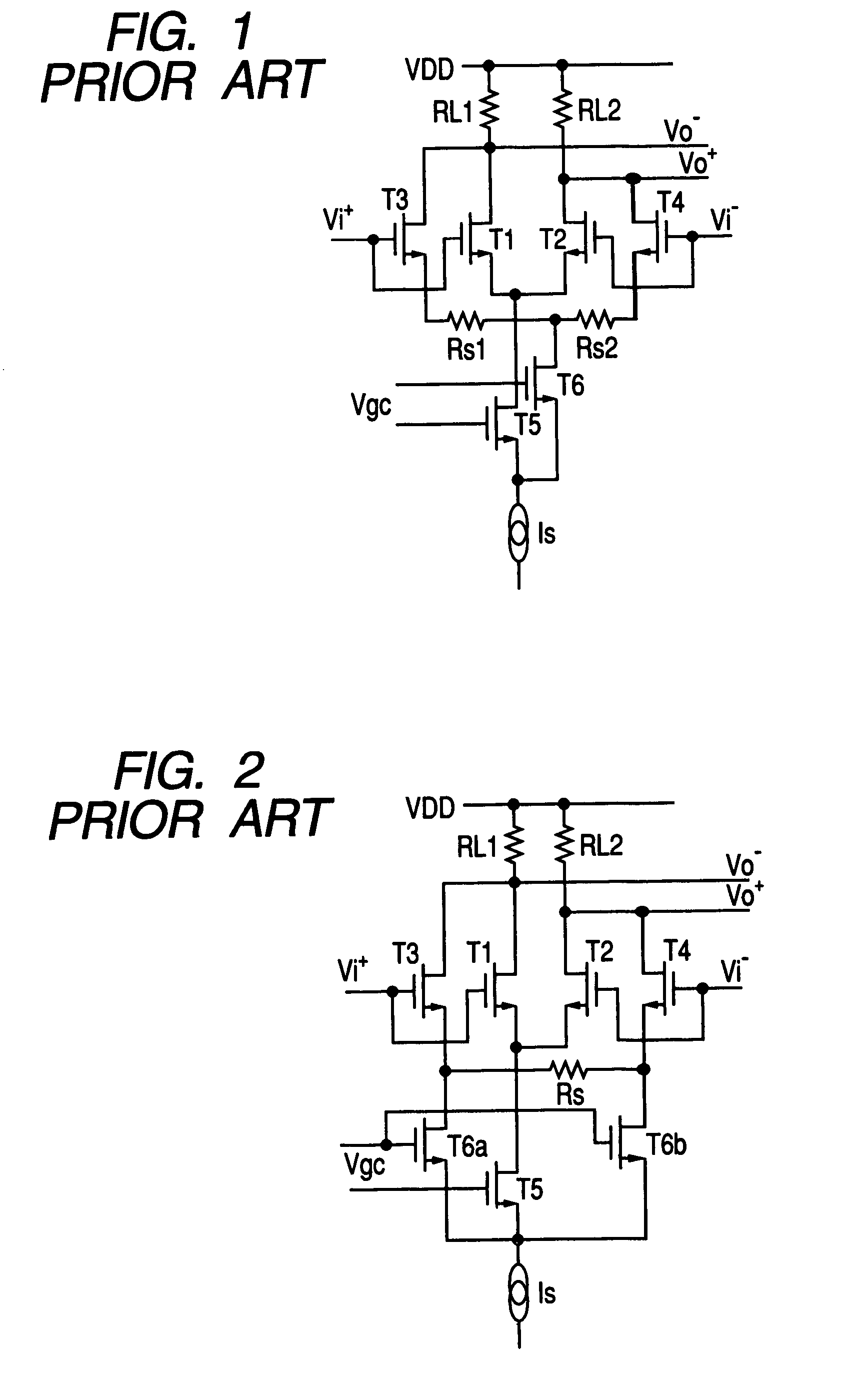
Besides, since the differential pairs based on the transistors T1-T4 and the differential pair of the transistors T5-T6 are serially connected between power source voltages, the minimum operating supply voltage cannot be made small, and hence, the variable gain amplifier is unsuited to a low supply voltage operation such as of battery drive (having a supply voltage of 1.5 V).
Therefore, as the amplifier circuit enters a large input potential (low gain operation) region, the AGC operation shifts to a limit amplification operation, and the linearity worsens.

Method used


Image

  • Variable gain amplifier, and AM-modulated signal reception circuit and detection circuit
  • Variable gain amplifier, and AM-modulated signal reception circuit and detection circuit
  • Variable gain amplifier, and AM-modulated signal reception circuit and detection circuit

Examples


first embodiment

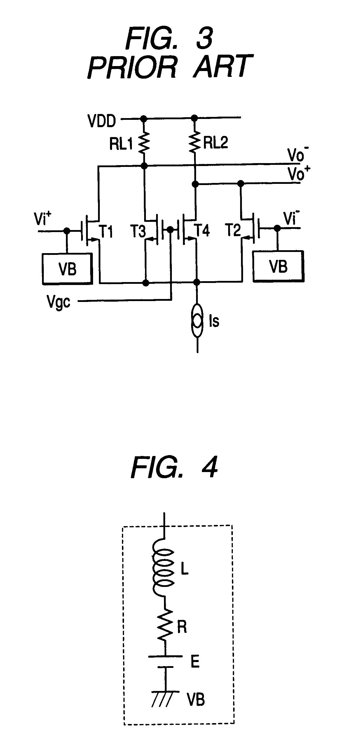
[0078]FIGS. 8-10 are circuit diagrams of variable gain amplifier circuits in the first embodiment of the present invention. The variable gain amplifier circuit in FIG. 8 includes a differential amplifier. The differential amplifier is so constructed that the gates of transistors T1 and T2 forming a differential pair are respectively connected to inputs Vi+ and Vi− (with a bias VB), that an absorption current circuit Is is connected to the sources of the transistors T1 and T2, and that load resistances RL1 and RL2 each having one end connected to a supply voltage VDD are respectively connected to the drains of the transistors T1 and T2. Besides, the drains and sources of transistors T3 and T4 are insertively connected between the sources of the respective transistors T1 and T2 of the differential pair and the absorption current circuit Is, and a gain control voltage Vgc is connected to the gates of the transistors T3 and T4.

[0079]The gate configurations of the transistors T1 and T2 a...

second embodiment

[0097]FIGS. 11A-11D are circuit diagrams of AM-modulated signal reception circuits in the second embodiment of the present invention. The AM-modulated signal reception circuit in FIG. 11A includes a gain control amplifier block GCA-B which lowers its gain when an input voltage Vp from a peak value input terminal is larger than a built-in reference value, and heightens its gain when the former is smaller than the latter, and which amplifies an input AM-modulated signal Vi with the gain so as to deliver an output signal Vo. Also included is an envelope detection circuit SDet which detects the envelope of the output signal Vo of the gain control amplifier block GCA-B. A comparator. circuit Comp compares the output of the envelope detection circuit SDet and a reference voltage VR2 so as to output a comparison result signal TCO. A peak detection circuit PDet receives the output signal TCO of the comparator circuit Comp as a control input. When the output signal TCO of the comparator circ...

third embodiment

[0124]FIGS. 12A-12E are circuit diagrams of AM-modulated signal reception circuits in the third embodiment of the present invention. The first construction of the AM-modulated signal reception circuit in the third embodiment is a construction (in FIG. 12A) in which, in the AM-modulated signal reception circuit in the second embodiment, a second resistance R3 (or constant current I3) for a discharge path for causing to flow a current smaller than that of the resistance R1 for the discharge path (or the constant current circuit I1 for the discharge path) is added to the peak holding capacitance C1 of the peak detection circuit PDet.

[0125]FIG. 12B shows the fact that the resistance R3 for the discharge path as shown in FIG. 12A can be replaced with the second constant current circuit I3 for the discharge path.

[0126]The second construction is a construction (in FIG. 12C) in which the turn-ON / OFF of the transfer gate TG1 is controlled through the OR synthesis between the output signal TC...


PUM


Abstract

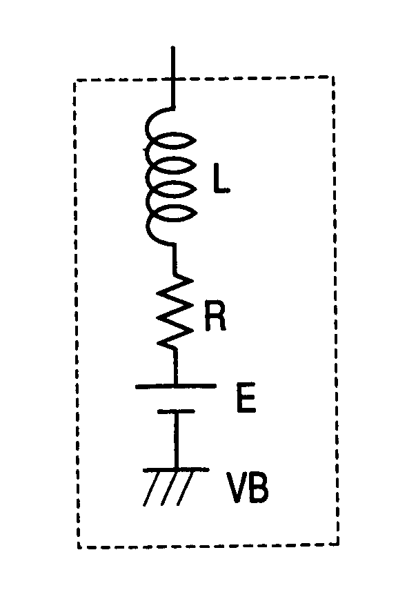
In order to provide a variable gain amplifier of enhanced linearity and wide variable gain range, an AM-modulated signal reception circuit in which the noise of an input portion is reduced so as to improve the follow-up characteristic of an AGC circuit, and an AM-modulated signal detection circuit which produces an output precisely corresponding to a peak value envelope, the variable gain amplifier comprises a differential input amplifier which includes transistors T1 and T2 (in FIG. 8) constituting a differential pair, and a constant current circuit Is operating as an absorption current circuit of the transistors T1 and T2, and a variable impedance which is connected between the sources of the respective transistors T1 and T2, wherein the gain of the differential input amplifier is made variable by variably controlling the value of the variable impedance.

Description

[0001]This application is Divisional of U.S. application Ser. No. 10 / 735,720 filed Dec. 16, 2003 now abandoned.BACKGROUND OF THE INVENTION[0002]1. Field of the Invention[0003]This invention relates to the circuits of reception portions for radio frequency (RF) communications employing AM modulation, such as the RF reception portion of a radio timepiece.[0004]2. Description of Related Art[0005]FIG. 1-FIG. 3 are circuit diagrams each showing a practicable example of a prior-art variable gain amplifier for auto gain control (AGC). Besides, FIG. 6 is a circuit diagram showing the basic constructional example of the RF reception portion of a prior-art radio timepiece.[0006]In the variable gain amplifier shown in FIG. 1, a differential amplifier 1 is so configured that transistors T1 and T2 constitute a first differential pair, the absorption current of which is caused to flow to the drain of a transistor T5. Also, a differential amplifier 2 is so configured that a transistor T3 having a ...

Claims


Application Information

Patent Timeline
Patent Type & Authority Patents(United States)
IPC IPC(8): H04B7/00G04G5/00G04R20/00G04R20/10H03G1/00H03G3/10H03G3/30H04B1/16
CPCH03F3/45197H03G1/0023H03F2203/45362H03F2203/45492
Inventor MIYASITA, TOKIOYANAGIHARA, JUNICHITAYA, TAKASHI
Owner SUMITOMO ELECTRIC IND LTD
Learn More