Valve assembly for a two-stroke engine

a two-stroke engine and valve assembly technology, applied in the field of valve assembly, can solve the problems of large increase of charge loss, torque decrease, and appreciable decrease of useful strok

Active Publication Date: 2010-07-27
BRP ROTAX
View PDF12 Cites 26 Cited by
  • Summary
  • Abstract
  • Description
  • Claims
  • Application Information

AI Technical Summary

Benefits of technology

[0010]It is also an object of the present invention to provide a movable valve assembly suitable for use with two or more exhaust ports of a two-stroke internal combustion engine with a reduced likelihood of having its movement impeded due to coking.
[0012]It is also an object of the present invention to provide a movable valve assembly suitable for use with two or more exhaust ports of a two-stroke internal combustion engine, wherein discrepancies in valve position between the exhaust ports are reduced.

Problems solved by technology

The adjustment of the exhaust port, to obtain maximum power capacity of the engine at high speeds involves, in the medium speed range, not only an appreciable decrease of the useful stroke, but also a large increase of the charge losses.
As a result, the torque decreases and the specific fuel consumption increases greatly.
The accumulation of coking deposits can impede the movement of the valve between the full flow position and the flow restricting position.
As a result, the actual position of the valve may differ from the desired position, resulting in reduced engine performance.
In addition, if the valve is not in the desired position due to coking or other impediments, its actual position is not easily determinable and it is difficult to adjust either the valve position or other aspects of engine performance such as the fuel-air ratio to be appropriate for the actual valve position.
As a result, some of the cylinders will have different performance characteristics, which can adversely affect engine performance, fuel economy and rider comfort, as well as causing premature wear to engine parts.

Method used


Image

  • Valve assembly for a two-stroke engine
  • Valve assembly for a two-stroke engine
  • Valve assembly for a two-stroke engine

Examples


first embodiment

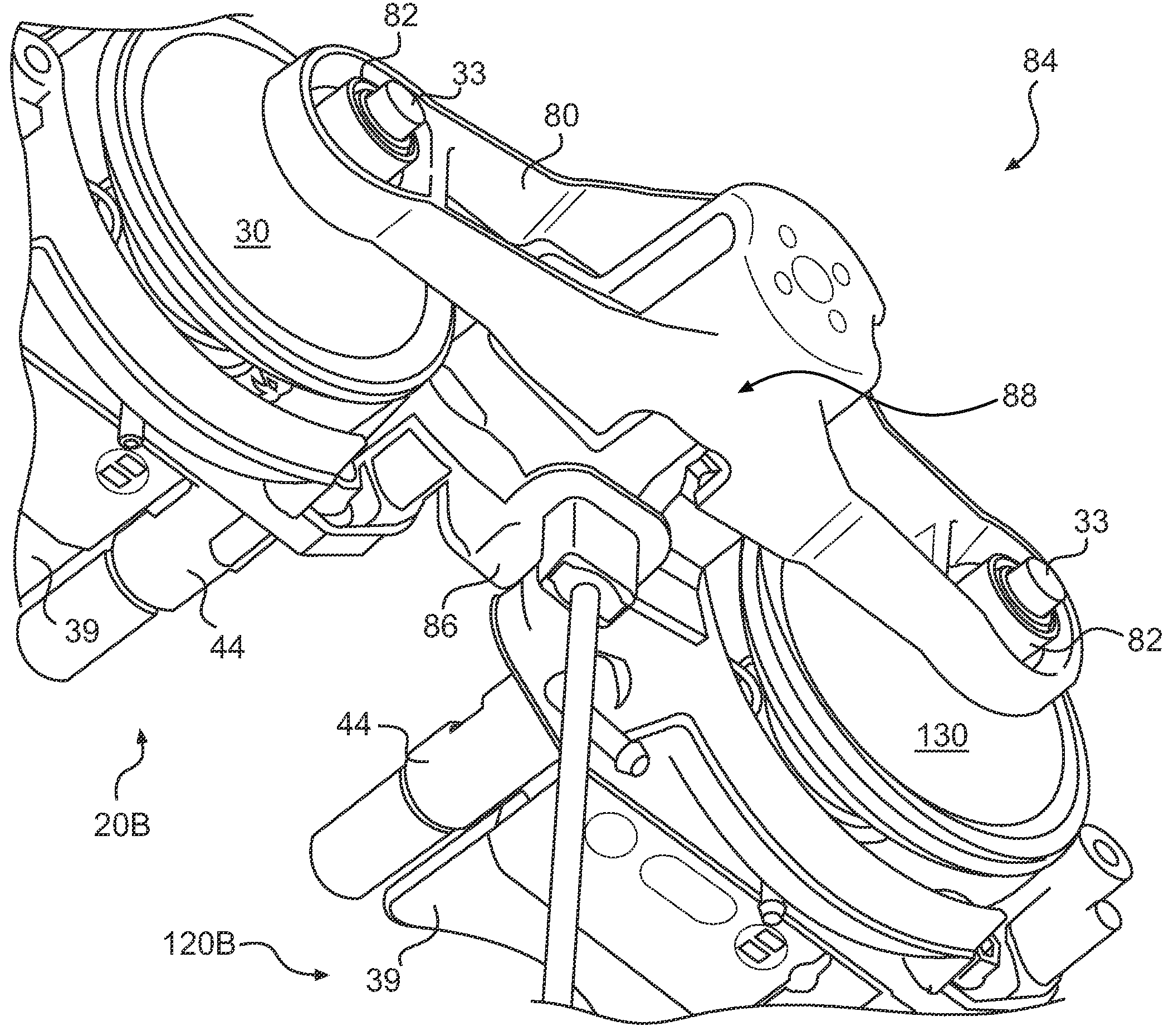
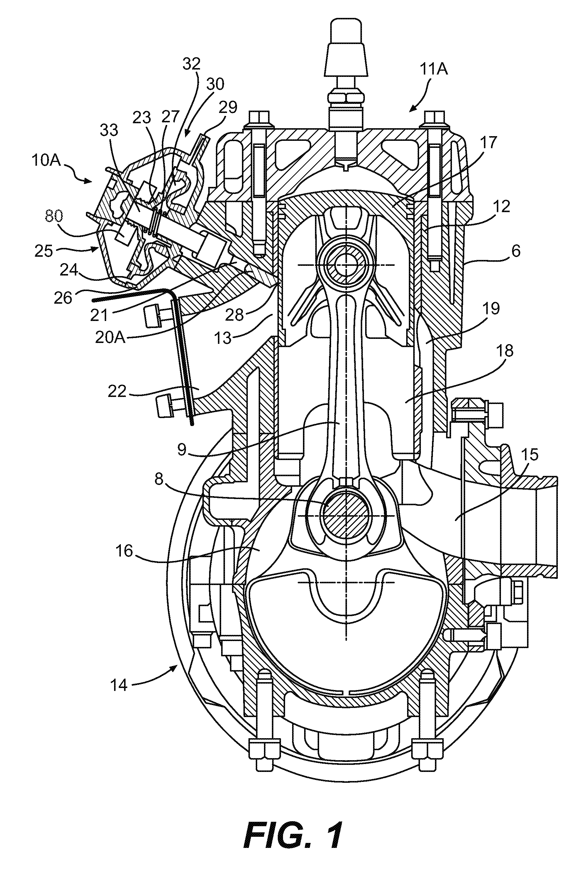
[0059]A valve assembly 10 in accordance with aspects of the present invention, which is described in greater detail below, comprises two valve actuators 30 and 130. A valve 20 is connected to the actuator 30 and a valve 120 is connected to the actuator 130. In FIG. 1, the valve assembly 10 is valve assembly 10A having the actuators 30, 130 (both of which can be seen in FIG. 11) and where the valves 20, 120 are one-part valves 20A, 120A. It is contemplated that the valves 20, 120 may alternatively both be actuated by a single actuator 30. As shown in FIG. 1 the valve assembly 10A is operatively connected to a two-cylinder two-stroke engine 11A. It should be understood that the two-stroke engine 11A may have more than two cylinders, as will be described below. The engine 11A comprises a crankcase 14 and a cylinder block 6 connected to the crankcase 14. Two cylinders 12 (both of which can be seen in FIG. 12), disposed in the cylinder block 6, each have a respective exhaust port 13. The...

second embodiment

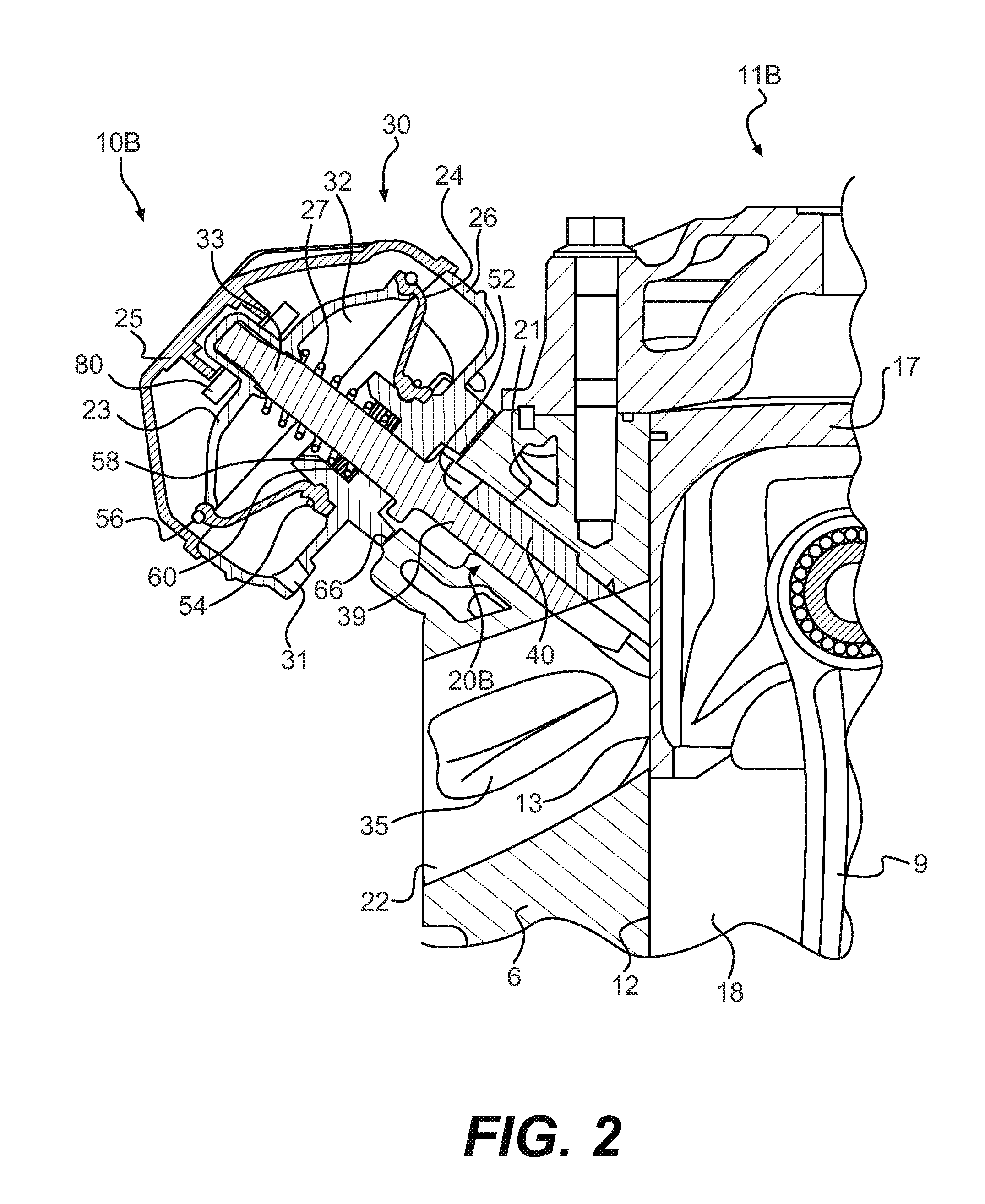
[0061]Turning now to FIG. 2, the valve assembly 10, valve assembly 10B, is shown which has the actuators 30 and where the valves 20, 120 are two-part valves 20B and 120B, described in greater detail below. As shown in FIG. 2 the valve assembly 10B is operatively connected to a two-stroke engine 11B. In addition to the components described above with respect to engine 11A, which have been labelled with the same reference numerals and which will not be described again, the engine 11B has, as best seen in FIGS. 9A to 9C, auxiliary exhaust ports 34 disposed so as to be symmetrical to the corresponding main exhaust port 13. The auxiliary exhaust ports 34 are connected to the exhaust passage 22 by way of auxiliary passages 35. Auxiliary guide channels (not shown) are provided parallel to the guide channel 21 in the area of the auxiliary passages 35 to receive auxiliary valves 44, described in greater detail below, which are associated with the two-part valve 20B.

[0062]Turning now to FIGS....


PUM


Abstract

A two-stroke internal combustion engine is disclosed having first and second cylinders having respective exhaust ports. A valve assembly comprises at least one valve actuator. First and second valves are operatively connected to the at least one valve actuator. The first and second valves are each movable between a first position wherein the valve extends a first distance in the respective exhaust port and a second position wherein the valve extends a second distance in the respective exhaust port. A valve connecting member is rigidly connected to the first and second valves and movable therewith via a translational motion while maintaining a substantially constant angular orientation relative to the cylinder block. A position sensor has a first portion connected to the cylinder block and a second portion connected to the valve connecting member. An electronic control unit (ECU) electrically connected to the position sensor.

Description

CROSS REFERENCE[0001]The present application claims priority to Canadian Patent Application 2,605,311 filed on Sep. 28, 2007, entitled “Exhaust Valve Position Feedback Control and Lubrication Thereof”, the entirety of which is incorporated herein by reference.FIELD OF THE INVENTION[0002]The present invention relates to a valve assembly suitable for use with the exhaust ports of a multi-cylinder two-stroke internal combustion engine.BACKGROUND OF THE INVENTION[0003]In order to ensure that two-stroke engines have a high power capacity at high speeds, a high volumetric efficiency is required and the charge losses must be minimized. This can be accomplished by an early and therefore higher opening of the exhaust passage into the cylinder. The adjustment of the exhaust port, to obtain maximum power capacity of the engine at high speeds involves, in the medium speed range, not only an appreciable decrease of the useful stroke, but also a large increase of the charge losses. As a result, t...

Claims


Application Information

Patent Timeline
Patent Type & Authority Patents(United States)
IPC IPC(8): F02B25/00
CPCF01L1/38F01L1/46F02D13/0284F02B2075/025Y02T10/18Y02T10/12
Inventor OKANOVIC, MIDHATZAUNER, GUNTHER
Owner BRP ROTAX
Why Eureka
Try Eureka