Flexible light source device and fabrication method thereof

a light source device and flexible technology, applied in the direction of semiconductor/solid-state device details, circuit optical details, printed circuit aspects, etc., can solve the problems of reduced flexibility of the substrate, reduced extraction efficiency of the entire ssl chip, and very limited light output of the device, and achieve the effect of high flexibility and slim appearance of the flexible light source devi

Inactive Publication Date: 2010-07-27
IND TECH RES INST
View PDF9 Cites 4 Cited by
  • Summary
  • Abstract
  • Description
  • Claims
  • Application Information

AI Technical Summary

Benefits of technology

[0009]As described above, in the present invention, a substrate and a molding compound are adopted in the flexible light source device and accordingly a high flexibility and a slim appearance of the flexible light source device are achieved.

Problems solved by technology

A SSL chip is anon-directional light source and accordingly the light output thereof is very limited.
Besides, because the substrate therein absorbs light, the extraction efficiency of the entire SSL chip is reduced.
However, the flexibility of the substrate will be reduced by aforementioned approaches.
Even though the large-sized SSL offers a higher light emitting efficiency, it produces more heat and accordingly the extraction efficiency thereof is reduced due to uneven current dispersion and heat accumulation.

Method used


Image

  • Flexible light source device and fabrication method thereof
  • Flexible light source device and fabrication method thereof
  • Flexible light source device and fabrication method thereof

Examples


Embodiment Construction

[0012]Reference will now be made in detail to the present preferred embodiments of the invention, examples of which are illustrated in the accompanying drawings. Wherever possible, the same reference numbers are used in the drawings and the description to refer to the same or like parts.

[0013]The present invention provides a flexible light source device having a high flexibility and a slim appearance. The present invention also provides a fabrication method for fabricating a flexible light source device having a high flexibility and a slim appearance.

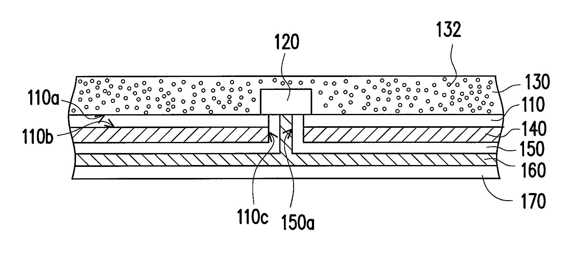
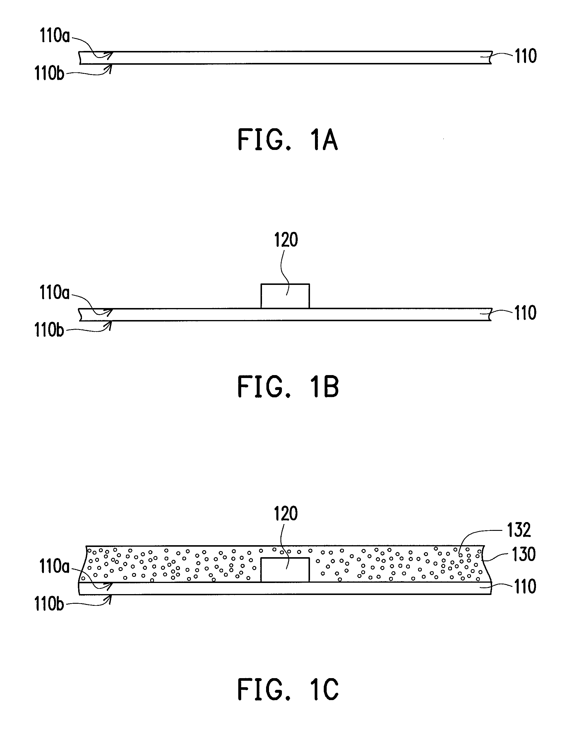
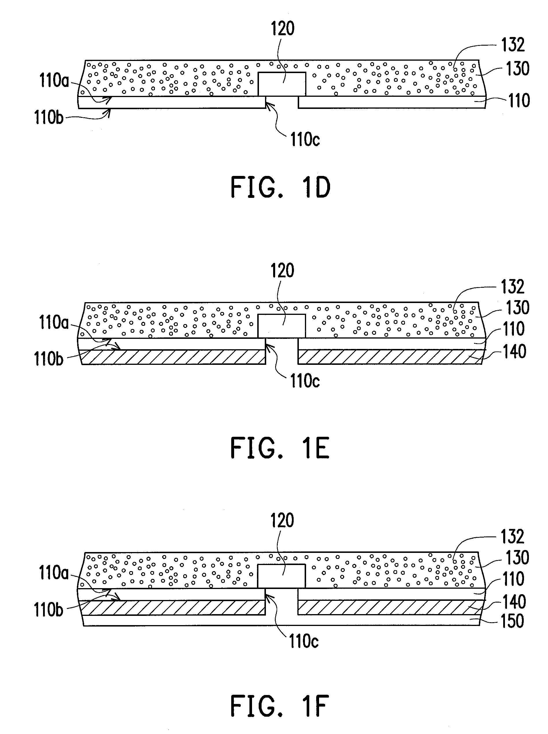
[0014]FIGS. 1A˜1I are flowcharts illustrating a fabrication method of a flexible light source device according to an embodiment of the present invention. In the present embodiment, the fabrication method of the flexible light source device 100 includes following steps. First, referring to FIG. 1A, a substrate 110 is provided, wherein the substrate 110 has a first surface 110a and a second surface 110b opposite to the first surface 110a....


PUM


Abstract

A flexible light source device including a substrate, a light emitting device, a molding compound, a dielectric layer, and a metal line is provided. The substrate has a first surface, a second surface opposite to the first surface, and a first opening. The light emitting device is disposed on the first surface of the substrate and covers the first opening. The molding compound is located above the first surface and covers the light emitting device. The dielectric layer is disposed on the second surface and covers a sidewall of the first opening. The dielectric layer has a second opening which exposes part of the light emitting device. The metal line is disposed on the dielectric layer, wherein the metal line is electrically connected to the light emitting device via the second opening in the dielectric layer. Additionally, a fabrication method of the flexible light source device is also provided.

Description

CROSS-REFERENCE TO RELATED APPLICATION[0001]This application claims the priority benefit of Taiwan application serial no. 97151124, filed on Dec. 26, 2008. The entirety of the above-mentioned patent application is hereby incorporated by reference herein and made a part of specification.BACKGROUND OF THE INVENTION[0002]1. Field of the Invention[0003]The present invention generally relates to a light source device and a fabrication method thereof, and more particularly, to a flexible light source device and a fabrication method thereof.[0004]2. Description of Related Art[0005]Solid state lighting (SSL) has many advantages such as small volume, high anti-shock ability, low power consumption, long lifespan, and high color diversity and purity, etc. Thereby, SSL has been broadly applied to various products. Because the designs of most application products are going towards high portability, those flexible products will certainly bring more convenience in their being carried around.[0006]...

Claims


Application Information

Patent Timeline
Patent Type & Authority Patents(United States)
IPC IPC(8): H01L29/267
CPCH05K1/0274H05K3/32H01L33/62H05K1/0203H01L2924/0002H05K1/189H05K3/284H05K2201/09481H05K2201/0969H05K2201/10106H05K2201/2054H05K2203/1316H05K2203/1469H01L2924/00
Inventor HSIAO, ZHI-CHENGHSU, CHAO-KAICHEN, YU-HUA
Owner IND TECH RES INST
Why Eureka
Try Eureka