
Universal digital channel for receiving signals of global navigation satellite systems

a global navigation satellite and digital channel technology, applied in satellite radio beaconing, measurement devices, instruments, etc., can solve problems such as multipath errors, complex operation of rover receivers, and ambiguity resolution of phase measurements, so as to reduce the number of elements

Active Publication Date: 2010-07-27
TOPCON GPS
View PDF11 Cites 36 Cited by
  • Summary
  • Abstract
  • Description
  • Claims
  • Application Information

AI Technical Summary

Benefits of technology

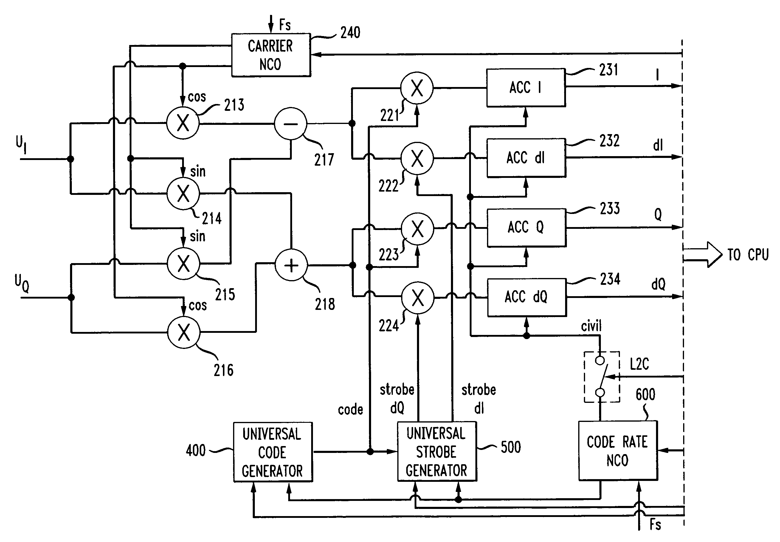
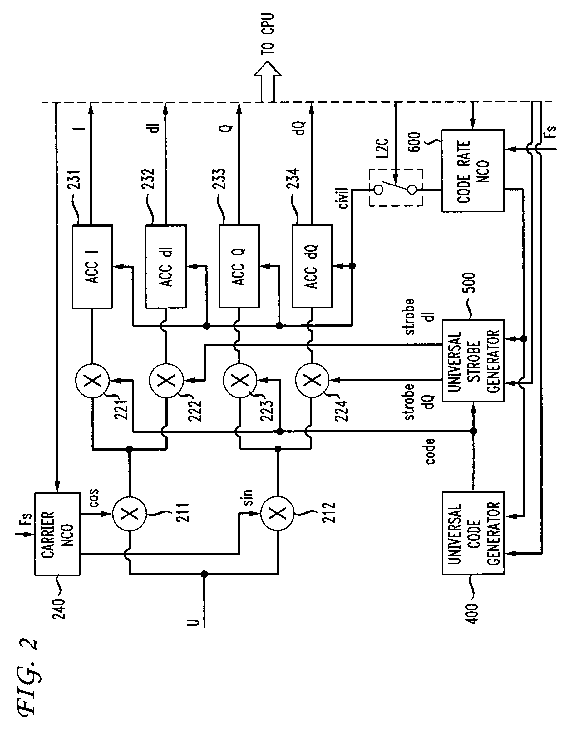
[0014]The strobe shape determines the extent of multipath suppression. The efficiency of multipath suppression may depend on both receiver RF-part filters and strobe parameters (shape and duration). The optimal strobe duration for a preset shape of strobe can be set for each RF-part by a trade-off between reducing multipath errors and increasing noise errors. The universal strobe generator can assign strobes of different shapes and duration. It enables the digital channel to be adapted for reception of signals from different navigation systems taking into account the features of the receiver RF-part.
[0017]In one embodiment, a frequency of a sub-carrier signal is coherent with a frequency of a code sequence generated by an m-sequence generator. Further, in one embodiment the frequency of the sub-carrier signal is greater than or equal to the frequency of the code sequence. The frequency of the code sequence may be generated by dividing the sub-carrier signal frequency by a dividing factor. The dividing factor may be, for example, equal to 1 . . . 8 with an interval of 0.5 and may therefore allow different binary offset carrier signals to be generated.
[0018]The strobe sequence is generated from single strobes which are repeated over time. The center of each single strobe coincides in time with the code chip boundary. The single strobe is a vector. The elements of this vector describe strobe shape and can take different values, such as one of the three possible values +1, −1 or 0. Each element has a specific duration, but the duration of the vector does not exceed chip duration. Different vectors correspond to the presence or absence of transition in the code sequence. The transition sign changes the vector sign. The duration of elements can be reduced by shortening the total strobe duration.

Problems solved by technology

The practical implementation of these advantages often encounters the problem of ambiguity resolution for phase measurements.
In many instances, the Rover receiver operates in a complicated environment in which various external influences cause measurement errors.
For example, external signals may interfere with the satellite signals, and structures and terrain may result in multipath errors.
Normal errors are related to a receiver fundamental error source and relatively weak signals which are reflected from local objects.
There are normal errors due to parasitic changes in wave propagation delay in atmosphere, inaccurate knowledge of satellite trajectories, onboard clock offset, thermal noise and other reasons.
Abnormal errors are large errors which may prevent the system from calculating an accurate location.
Such abnormal errors are occasionally a consequence of occasional spikes of intrinsic noise.
More often, however, they are the result of exposure of the receiver to some type of interference.
For example, strong reflected signals and extreme radio interference can cause abnormal errors.
Short-term partial shading of the Rover receiver by a local object may also considerably increase measurement errors in one or more “shaded” satellite channels due to radio wave diffraction.
If a satellite is completely shaded (i.e., blocked), tracking in the channel is interrupted, and the measured delay drifts because of reflected, still unshaded signals.
Dynamic effects on the receiver (i.e., certain motion of the Rover) may also cause abnormal errors.
Impulse accelerations or jerks impact both the receiving antenna and the quartz of the local reference oscillator and may result in the drift of the intermediate carrier frequency and measured phase.
One specific type of abnormal error is a cycle slip in phase lock loop (PLL) circuits of the receiver.

Method used


Image

  • Universal digital channel for receiving signals of global navigation satellite systems
  • Universal digital channel for receiving signals of global navigation satellite systems
  • Universal digital channel for receiving signals of global navigation satellite systems

Examples


Embodiment Construction

[0028]Different satellite systems typically transmit signals in frequency bands that are relatively close together (1560-1605, 1150-1280 MHz). Both the GPS and GLONASS satellites transmit a signal known as a Pseudo Random Noise (PRN) code which spreads the spectrum of signals and allows ranges to be measured. The power levels of the received signals are lower than intrinsic noise in the input band of the receiver.

[0029]In accordance with an aspect of the present invention, a receiver can receive signals from many satellite systems. When processing signals received from a plurality of satellites, the receiver can take into account the similarities and differences of the signals.

[0030]For example, if the receiver simultaneously receives signals from GLONASS satellites and GPS satellites, the receiver may determine that:[0031]Both types of satellites (i.e., GLONASS satellites and GPS satellites) transmit on two frequency bands, called L1 and L2.[0032]Both types of satellites transmit P...


PUM


Abstract

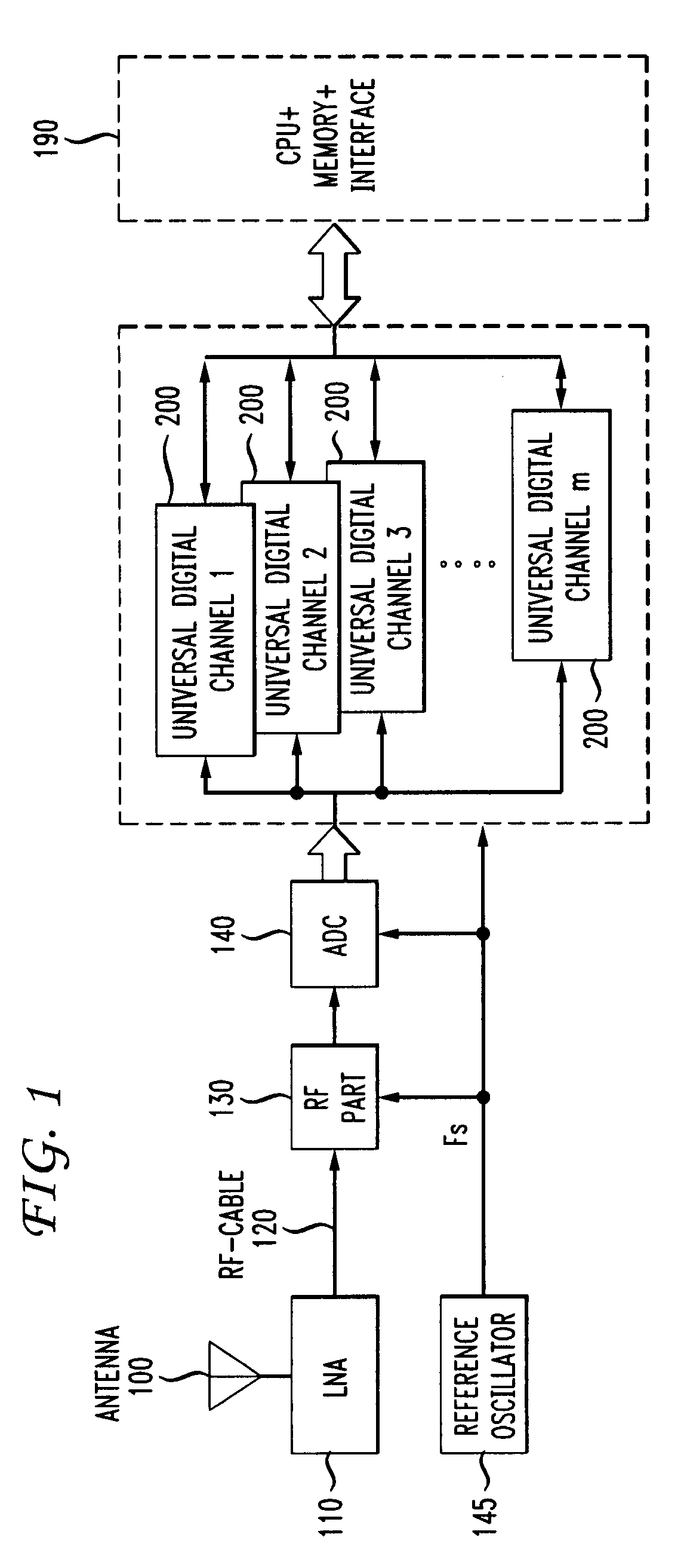
Disclosed is a system and method for processing signals received from different global navigation satellite systems. The receiver includes a number of universal digital channels. The universal digital channel can be used to receive and process different code signals of each of the three navigation satellite systems GPS, GLONASS, and GALILEO. The universal digital channels have the same structure. Each of them can be tuned to receive different signals. The core of the universal digital channel is a code generator and a universal strobe generator.

Description

[0001]This application claims the benefit of U.S. Provisional Application No. 60 / 790,470 filed Apr. 7, 2006, which is incorporated herein by reference.FIELD OF THE INVENTION[0002]The present invention relates generally to receivers and more particularly to a receiver of signals from global navigation satellite systems (GNSS).BACKGROUND OF THE INVENTION[0003]Satellite positioning systems are typically used to accurately determine the position of users possessing special navigation receivers. A navigation receiver receives and processes radio signals transmitted by satellites located within a line-of-sight distance of the receivers. The satellite signals include carrier signals that are modulated by pseudo-random binary codes.[0004]The receiver measures the time delay of the received signal relative to a local reference clock or oscillator. Code measurements enable the receiver to determine the so-called pseudo-ranges between the receiver and the satellites. The pseudo-ranges are diff...

Claims


Application Information

Patent Timeline
Patent Type & Authority Patents(United States)
IPC IPC(8): G01S19/33G01S19/37
CPCG01S19/33G01S19/37
Inventor VEITSEL, ANDREYZHDANOV, ALEXEYKIRSANOV, ALEXANDERZHODZISHSKY, MARK I.VEITSEL, VICTOR A.ORLOVSKY, IGORRUBTSOV, DMITRY
Owner TOPCON GPS
Learn More