Magneto-resistance effect element and thin-film magnetic head having non-magnetic spacer layer composed of one semiconductor layer and two metal layers

a technology of magnetic head and resistance effect, which is applied in the direction of magnetic recording, instruments, data recording, etc., can solve the problems of extremely short life span, extremely difficult to form the element at a high dimensional accuracy, and the loss of the magnetic resistance effect element, etc., and achieves the effect of higher mr ratio

Inactive Publication Date: 2010-07-27
TDK CORPARATION
View PDF8 Cites 4 Cited by
  • Summary
  • Abstract
  • Description
  • Claims
  • Application Information

AI Technical Summary

Benefits of technology

[0018]According to this structure, since a semiconductor layer is provided in the spacer layer, resistance can be made large without lowering the MR ratio, and with a low current density, a large output voltage can be obtained. Further, since the diffusion of Cu in the spacer layer into the semiconductor layer is suppressed by Pt, a larger MR ratio can be obtained.
[0021]When the semiconductor layer has a thickness ranging from a minimum of 1.0 nm to a maximum of 2.5 nm, an appropriate RA value can be obtained so that the spin transfer torque becomes small and electric noise becomes small.
[0023]When CuPt that makes up the first and second non-magnetic metal layers contains Pt ranging from a minimum of 5 at % to a maximum of 25 at %, the effect of suppressing the diffusion of Cu into the semiconductor layer is large due to the crystal structure.

Problems solved by technology

When the element is operated at the high current density, an electro-migration phenomenon occurs in which a metallic atom colliding with an electron migrates, and there is a fear that the magneto-resistance effect element will be destroyed by the migration of the atom and its life span becomes extremely short.
Further, when the element is operated at the high current density, an output noise caused by a spin transfer torque occurs, and a practical problem arises.
However, such a confined-current-path type magneto-resistance effect element has been difficult to manufacture, and it was extremely difficult to form the element at a high dimensional accuracy so as to be able to obtain desired performance.

Method used


Image

  • Magneto-resistance effect element and thin-film magnetic head having non-magnetic spacer layer composed of one semiconductor layer and two metal layers
  • Magneto-resistance effect element and thin-film magnetic head having non-magnetic spacer layer composed of one semiconductor layer and two metal layers
  • Magneto-resistance effect element and thin-film magnetic head having non-magnetic spacer layer composed of one semiconductor layer and two metal layers

Examples


Embodiment Construction

[0042]Embodiments of the present invention will be described below with reference to the drawings.

[Configuration of Thin-Film Magnetic Head]

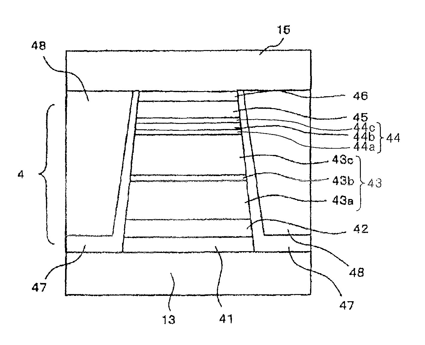
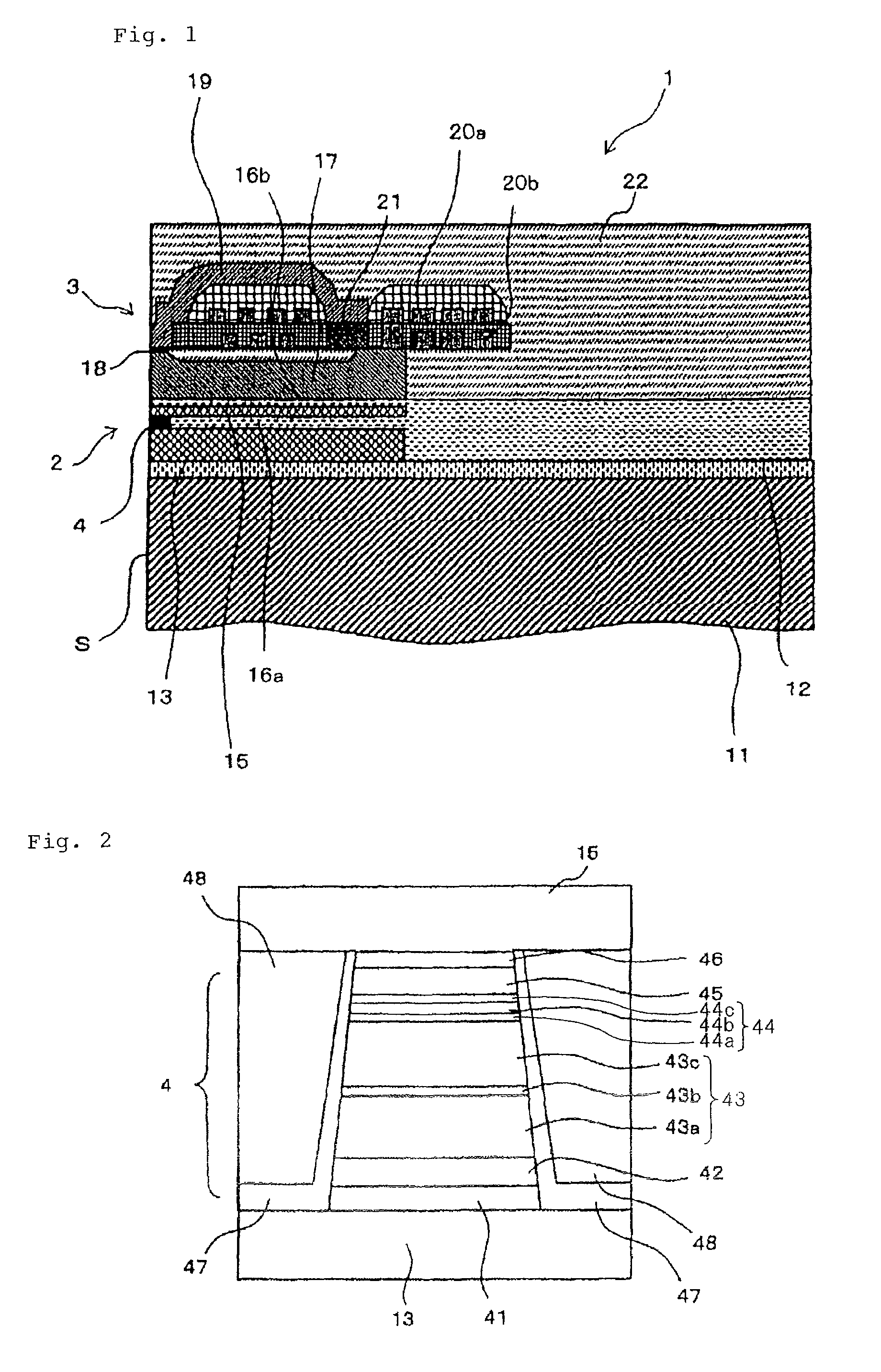
[0043]FIG. 1 conceptually shows a cross-sectional view of a major portion of a thin-film magnetic head having a magneto-resistance effect element according to the present invention.

[0044]Thin-film magnetic head 1 according to the present embodiment has substrate 11, reproducing unit 2 which reads data from a recording medium (not shown) and which is formed on substrate 11, and recording unit 3 for writing data on a recording medium (not shown) and which is formed on substrate 11.

[0045]Substrate 11 is made of Al2O3.TiC (AlTiC) that has excellent wear resistance. Base layer 12 made of alumina is disposed on an upper surface of substrate 11, and reproducing unit 2 and recording unit 3 are stacked on base layer 12.

[0046]Lower shield layer 13 made of a magnetic material such as Permalloy (NiFe), for example, is disposed on base layer 12. CPP-GMR elem...


PUM

PropertyMeasurementUnit
thicknessaaaaaaaaaa
thicknessaaaaaaaaaa
thicknessaaaaaaaaaa

Abstract

A magneto-resistance effect element used for a thin film magnetic head is configured by a buffer layer, an anti-ferromagnetic layer, a pinned layer, a spacer layer, a free layer, and a cap layer, which are laminated in this order, and a sense current flows through the element in a direction orthogonal to the layer surface, via a lower shield layer and a upper shield layer. The pinned layer comprises an outer layer in which a magnetization direction is fixed, a non-magnetic intermediate layer, and an inner layer which is a ferromagnetic layer. The spacer layer comprises a first and second non-magnetic metal layer, and a semiconductor layer. The first and second non-magnetic metal layer and comprise CuPt films having a thickness of more than 0 nm but no more than 2.0 nm, and the Pt content ranges from a minimum of 5 to a maximum of 25 at %.

Description

BACKGROUND OF THE INVENTION[0001]1. Field of the Invention[0002]The present invention relates to a magneto-resistance effect element and a thin-film magnetic head.[0003]2. Description of the Related Art[0004]Magnetic disk drives employ a thin-film magnetic head having a magneto-resistance effect element (MR element) for reading magnetic signals. In recent years, efforts have been made to design magnetic disk drives for higher recording densities, and accordingly there are growing demands for thin-film magnetic heads, particularly magneto-resistance effect elements, which satisfy higher-sensitivity and higher-output requirements.[0005]A CIP-GMR (Current in Plane-Giant Magneto-resistance) element which is a giant magneto-resistance effect element having a nonmagnetic layer between ferromagnetic layers and passing a sensing current in parallel to a layer surface, has been conventionally developed as a reproducing element in a thin-film magnetic head. On the other hand, a magnetic head ...

Claims


Application Information

Patent Timeline
Patent Type & Authority Patents(United States)
IPC IPC(8): G11B5/33
CPCG11B5/59683
Inventor MIZUNO, TOMOHITOHIRATA, KEITSUCHIYA, YOSHIHIROSHIMAZAWA, KOJI
Owner TDK CORPARATION
Why Eureka
Try Eureka