Plasma processing apparatus

a processing apparatus and plasma technology, applied in the direction of electrical apparatus, basic electric elements, electric discharge tubes, etc., can solve the problems of deterioration of the film on the specimen, erosion of the micropattern, and not always desirable to put the protective cover on the outer edge of the specimen, so as to achieve the effect of efficiently removing the film and without adversely affecting other portions

Inactive Publication Date: 2010-08-03
HITACHI HIGH-TECH CORP
View PDF22 Cites 8 Cited by
  • Summary
  • Abstract
  • Description
  • Claims
  • Application Information

AI Technical Summary

Benefits of technology

[0015]The plasma processing apparatus according to the present invention has the structure described above and can efficiently remove a deposited film on the outer edge of the backside of a specimen without adversely affecting other portions.

Problems solved by technology

In the method according to the Japanese Unexamined Patent Application Publication No. 2004-200353, the gas that eliminates the deposited film diffuses into a processing chamber and may cause deterioration of a film on the specimen or erosion of a micropattern.
Thus, it is not always desirable to put the protective cover on the outer edge of the specimen during the plasma processing.

Method used


Image

  • Plasma processing apparatus
  • Plasma processing apparatus
  • Plasma processing apparatus

Examples


first embodiment

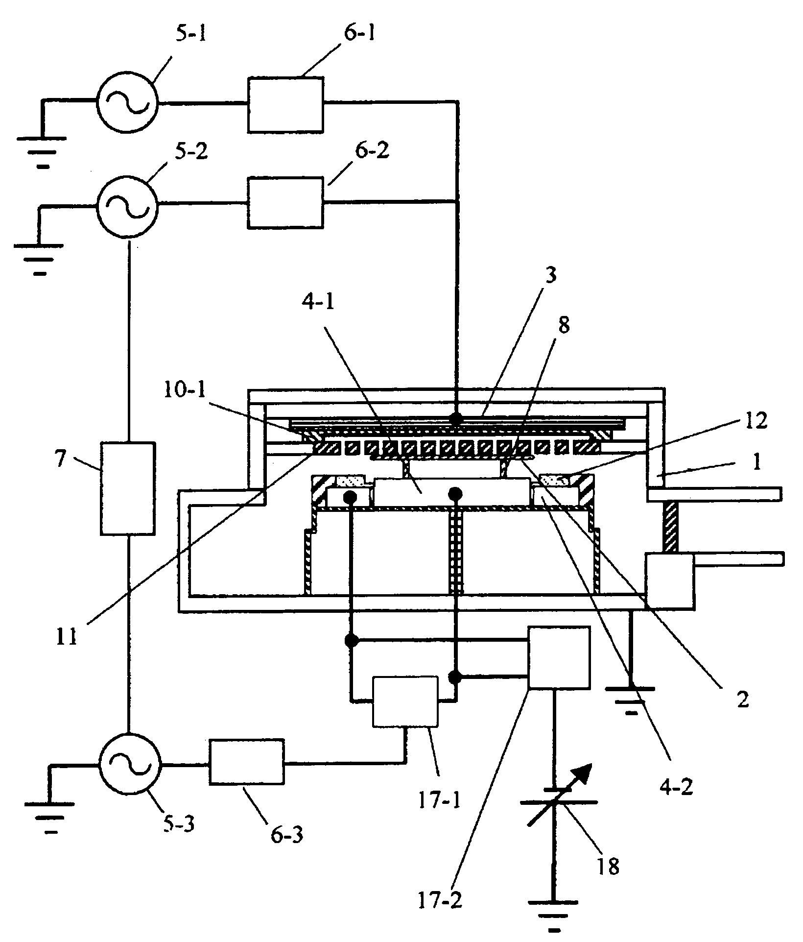
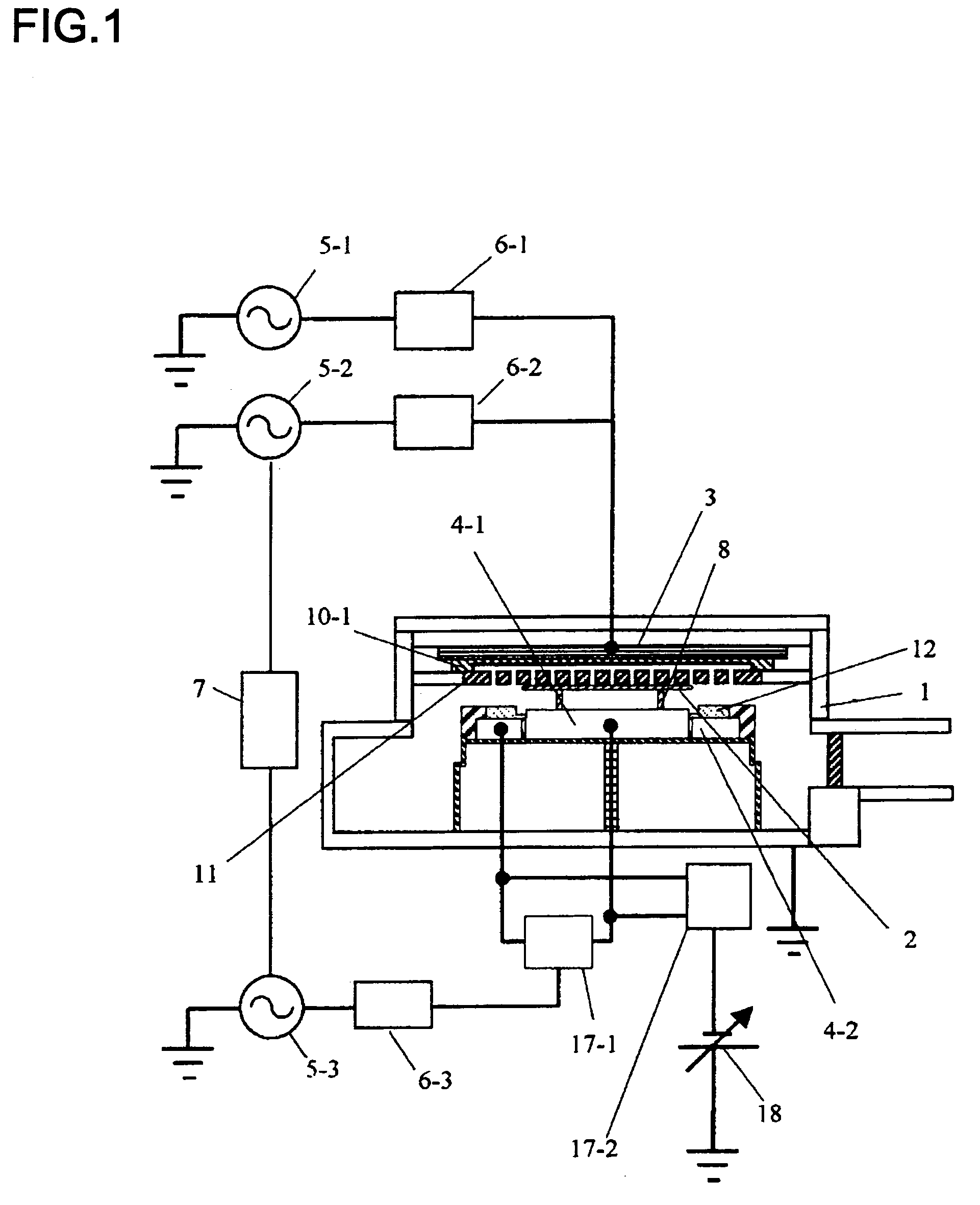
[0028]Preferred embodiments of the present invention will be described below with reference to the accompanying drawings. FIG. 1 is a schematic view of a plasma processing apparatus according to the present invention. In FIG. 1, the present invention is applied to a parallel-plate ECR plasma processing apparatus.

[0029]As shown in FIG. 1, in a vacuum processing chamber 1, a generally discoidal antenna electrode 3 for electromagnetic radiation and a mounting electrode 4 (an inner area 4-1 and an outer area 4-2) for mounting a specimen 2 face each other in parallel. A first high-frequency power source 5-1 for generating plasma is coupled to the antenna electrode 3 through a first matching transformer 6-1. The frequency of the first high-frequency power source 5-1 is, for example, in the range of 100 to 500 MHz. A coil (not shown) and a yoke (not shown) are disposed outside the vacuum processing chamber 1 and generate a magnetic field. The resulting magnetic field increases the efficien...

second embodiment

[0045]FIG. 5 is a schematic view of a plasma processing apparatus according to the present invention. In this embodiment, the present invention is applied to a plasma processing apparatus in which both a first high-frequency power source 5-1 for generating plasma and a third high-frequency power source 5-3 for accelerating ions incident on a specimen 2 are coupled to a mounting electrode 4. The same components as in FIG. 1, such as a direct-current power source 18 for electrostatically fixing the specimen 2 on the inner area 4-1, will not be further explained.

[0046]When the outer edge of the backside of the specimen 2 is cleaned, the electric power from the first high-frequency power source 5-1 can be applied to the outer area 4-2 to generate annular plasma (cleaning plasma) along the outer edge of the backside of the specimen 2. In this embodiment, since high-frequency electric power for generating plasma can be applied to a focus ring 12, the density and the gas pressure of the cl...

third embodiment

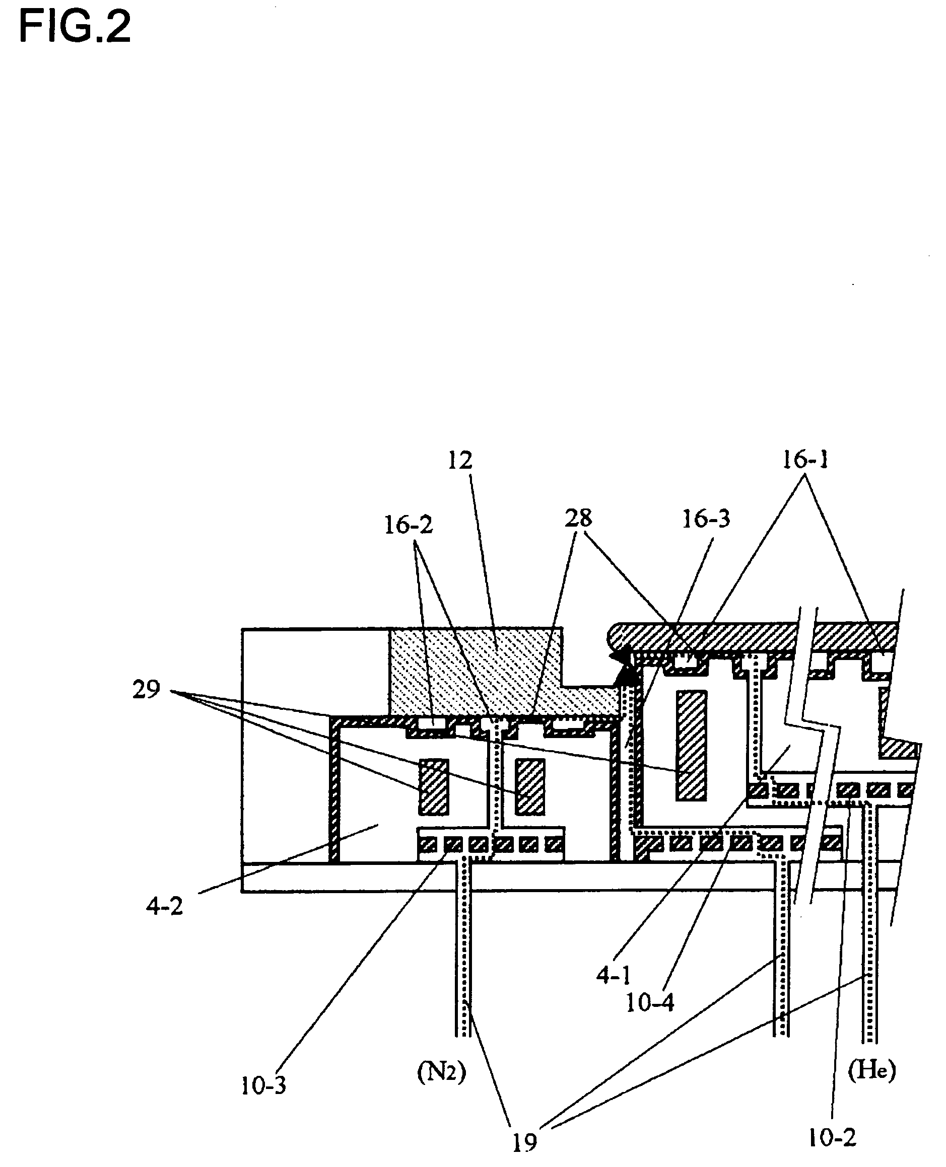
[0047]FIG. 6 is a schematic view of a plasma processing apparatus according to the present invention. In this embodiment, a focus ring 12 includes an inner focus subring 12-1 and an outer focus subring 12-2. The inner focus subring 12-1 is disposed directly under the outer edge of the backside of a specimen 2. The inner focus subring 12-1 and the outer focus subring 12-2 are placed on outer areas 4-2 and 4-3, respectively.

[0048]When the outer edge of the backside of a specimen 2 is cleaned, the electric power from a high-frequency power source 5 is divided into three portions with an electric power distributor 17: each portion is supplied to an inner area 4-1 and the outer areas 4-2 and 4-3. The electric power supplied to the inner area 4-1 and the outer areas 4-2 and 4-3 can be controlled independently.

[0049]The high-frequency electric power applied to the inner focus subring 12-1 through the outer area 4-2 can generate plasma predominantly directly under the outer edge of the back...


PUM

PropertyMeasurementUnit
frequencyaaaaaaaaaa
diameteraaaaaaaaaa
diameteraaaaaaaaaa

Abstract

A plasma processing apparatus includes a vacuum processing chamber, supplying means for introducing a processing gas into the vacuum processing chamber, a mounting electrode in the vacuum processing chamber for mounting a specimen on the mounting electrode, and a pusher pin for raising the specimen placed on the mounting electrode and holding the specimen over the mounting electrode, wherein the mounting electrode includes an inner area for mounting the specimen, an outer area for mounting a focus ring, and a high-frequency power source for supplying electric power to the inner area and the outer area, and wherein high-frequency electric power is applied to the outer area to generate plasma at the outer edge of the backside of the specimen while the specimen is raised with the pusher pin.

Description

[0001]The present application is based on and claims priority of Japanese patent application No. 2005-138519 filed on May 11, 2005, the entire contents of which are hereby incorporated by reference.BACKGROUND OF THE INVENTION[0002]1. Field of the Invention[0003]The present invention relates to a plasma processing apparatus, and more particularly to a plasma processing apparatus including a mechanism for cleaning the outer edge of the backside of a specimen.[0004]2. Description of the Related Art[0005]In a process for manufacturing a semiconductor device, such as a DRAM or a microprocessor, plasma etching, plasma CVD, and plasma ashing utilizing a weakly ionized plasma are widely used. To improve the yield in the manufacturing process of the semiconductor device, it is important to reduce particles adhering to the specimen during the plasma processing.[0006]In recent years, as semiconductor devices have been downsized, processing gases that tend to build up a deposition layer on a sp...

Claims


Application Information

Patent Timeline
Patent Type & Authority Patents(United States)
IPC IPC(8): C23F1/00
CPCC23F4/00H01J37/32009H01J37/32532H01J37/32642H01L21/02087H01L21/67109H01L21/6831H01L21/68707H01L21/68742
Inventor KOBAYASHI, HIROYUKIIZAWA, MASARUYOKOGAWA, KENETSUTAMURA, TOMOYUKIMAEDA, KENJI
Owner HITACHI HIGH-TECH CORP
Why Eureka
Try Eureka