
Ionization gauge with a cold electron source

a technology of ionization gauge and electron source, which is applied in the direction of instruments, heat measurement, fluid pressure measurement, etc., can solve the problems of reducing the operational life of the gauge, affecting the operation of the gauge, and failing to meet the emission characteristics of the gauge's electron sour

Active Publication Date: 2010-08-03
MKS INSTR INC
View PDF55 Cites 21 Cited by
  • Summary
  • Abstract
  • Description
  • Claims
  • Application Information

AI Technical Summary

Benefits of technology

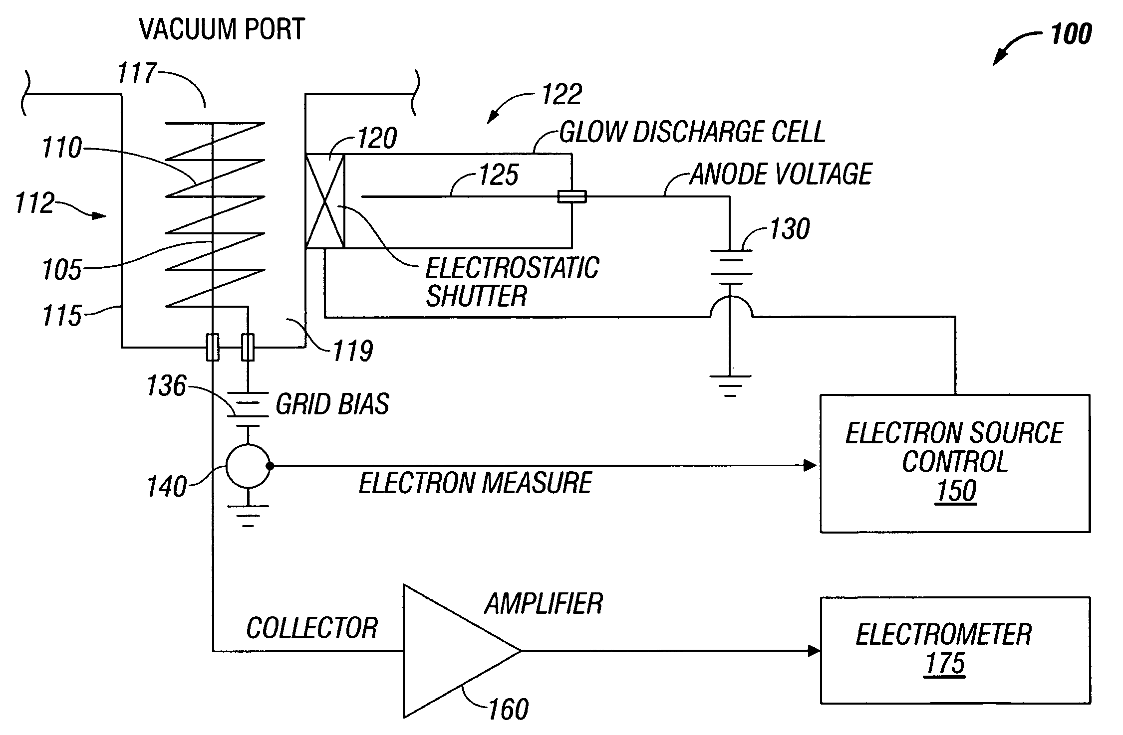
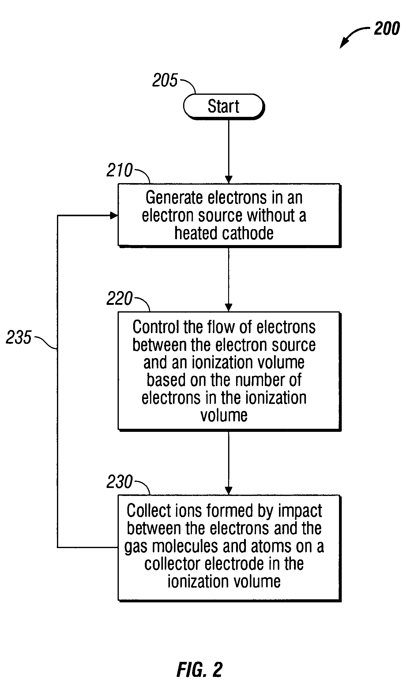
The present invention provides an ionization gauge and method that eliminates the hot cathode or filament, while maintaining the same level of precision in gas density measurements. The ionization gauge includes a cold electron source, a collector electrode, and an electrostatic shutter that controls the flow of electrons between the electron source and an ionization volume. The collector electrode then collects ions formed by the impact between the electrons and gas molecules in the ionization volume. The ionization gauge may also include multiple collector electrodes and an annular ring of electrostatic shutters. The method involves generating electrons, regulating the flow of electrons from a source to the ionization volume, controlling the energy of the electrons, and collecting ions. The technical effects of the invention include improved accuracy and reliability of gas density measurements, reduced risk of damage to the ionization gauge, and improved stability of the electron source.

Problems solved by technology

However, these same gauges fail in hours or even minutes when operated at too high a pressure or in gas types that degrade the emission characteristics of the gauge's electron source (hot cathode).
Examples of such hot cathode interactions leading to decreased operational lifetime range from degradation of the electron emission properties of the oxide coating on the hot cathode to exposure to water vapor.
Degradation of the oxide coating dramatically reduces the number of electrons generated by the cathode, and exposure to water vapor results in the complete burnout of a tungsten cathode.
However, cold cathode gauges suffer from relatively large inaccuracies due to uncontrolled discharge of electrons and surface phenomena.

Method used


Image

  • Ionization gauge with a cold electron source
  • Ionization gauge with a cold electron source
  • Ionization gauge with a cold electron source

Examples


Embodiment Construction

[0016]A description of preferred embodiments of the invention follows.

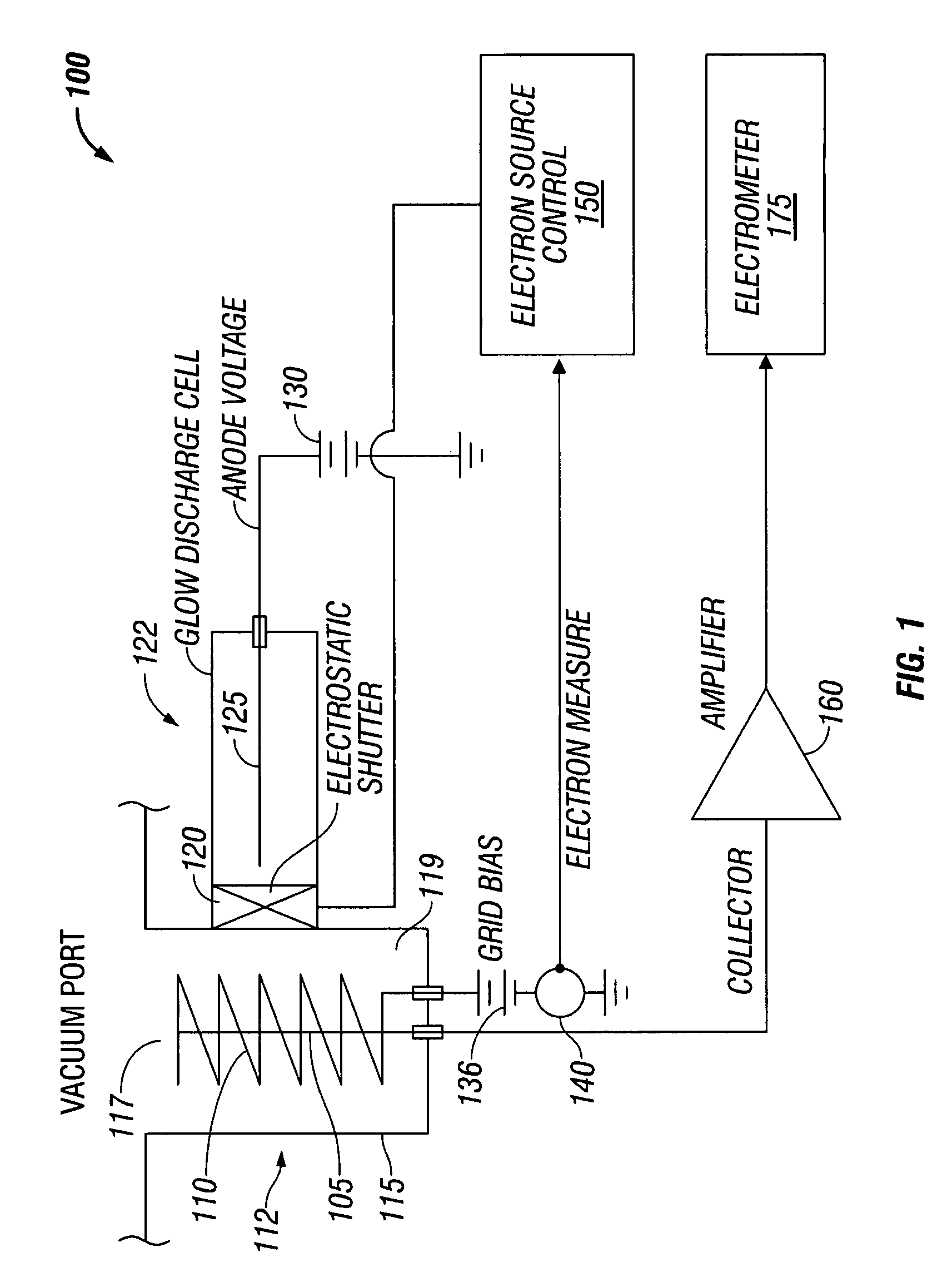
[0017]As shown in FIG. 1, an ionization gauge 100 according to an embodiment includes a typical B-A ionization gauge 112 without a hot cathode but with a cold electron source 122. The B-A ionization gauge 112 may be a nude or non-nude type ionization gauge. The cold electron source 122 may be a cold cathode ionization gauge such as a glow discharge cell, of which one version is the inverted magnetron. The glow discharge cell generates an electron cloud using crossed electrostatic and magnetic fields. Other cold cathode ionization gauges that may be used as the cold electron source 122 include the Penning gauge, magnetron and the double inverted magnetron.

[0018]Generally, the inverted magnetron type gauge has two electrodes with an electric field between them caused by an anode being positive with respect to a cathode. Likewise, the cathode is negative with respect to the anode. The inverted magnetron type gauge is...


PUM

PropertyMeasurementUnit
temperatureaaaaaaaaaa
volumeaaaaaaaaaa
ionization volumeaaaaaaaaaa

Abstract

An ionization gauge that eliminates a hot cathode or filament, but maintains a level of precision of gas density measurements approaching that of a hot cathode ionization gauge. The ionization gauge includes a collector electrode disposed in an ionization volume, an electron source without a heated cathode, and an electrostatic shutter that regulates the flow of electrons between the electron source and the ionization volume. The electrostatic shutter controls the flow of electrons based on feedback from an anode defining the ionization volume. The electron source can be a Penning or glow discharge ionization gauge.

Description

BACKGROUND OF THE INVENTION[0001]Hot cathode ionization gauges are the most common non-magnetic means of measuring very low pressures and the most widely used version worldwide was disclosed in U.S. Pat. No. 2,605,431 in 1952. A typical ionization gauge includes an electron source or a cathode. The electrons emitted by the electron source collide with gas atoms and molecules in an ionization volume and produce ions. The rate at which the ions are formed is directly proportional to the density of the gas (pressure at a constant temperature) in the gauge.[0002]Two types of ionization gauges exist: hot cathode and cold cathode. The most common hot cathode ionization gauge is the Bayard-Alpert (B-A) gauge. The B-A gauge includes a heated filament (cathode) that emits electrons toward a cylindrical wire grid (anode) defining an ionization volume (anode volume). The temperature spread for most commonly used cathodes is about 1,500 degrees Celsius to about 2,200 degrees Celsius. An ion col...

Claims


Application Information

Patent Timeline
Patent Type & Authority Patents(United States)
IPC IPC(8): G01L21/30G01L21/32H05B31/26
CPCG01L21/34H01J41/02
Inventor KNOTT, RICHARD A.BRUCKER, GERARDO A.ARNOLD, PAUL C.
Owner MKS INSTR INC
Learn More