Surface-mount type crystal oscillator

a crystal oscillator and surface-mount technology, applied in the direction of oscillator, pulse generator, pulse technique, etc., can solve the problems of ic chip b>2/b> electrical damage, manufacturing process, and other electronic devices that affect the above configuration, so as to prevent electrical damage to the ic chip, improve the dld characteristics, and apply high voltage to the oscillation circuit

Inactive Publication Date: 2010-08-03
NIHON DEMPA KOGYO CO LTD
View PDF5 Cites 8 Cited by
  • Summary
  • Abstract
  • Description
  • Claims
  • Application Information

AI Technical Summary

Benefits of technology

[0021]It is an object of the present invention to provide a surface-mount type crystal oscillator that can prevent change in vibration characteristics caused by an inspection terminal for inspecting the characteristics of a crystal blank, and has improved productivity.
[0023]According to such a configuration, the electrical connection between a crystal blank and inspection terminals can be switchably turned on or turned off by the selecting signal supplied from outside. By disconnecting the electrical connection between the crystal blank and the inspection terminals after the vibration characteristics of the crystal blank have been measured using the inspection terminal, electrical effects from a wiring pattern or other electronic parts on a wiring board can be prevented when the crystal oscillator is mounted on the wiring board.
[0024]In the crystal oscillator according to the present invention, second switching means may be provided for switchably electrically connecting and disconnecting the crystal blank to and from the oscillator circuit in accordance with the selecting signal. By providing the second switching means, the crystal blank can be electrically isolated from the oscillation circuit when the vibration characteristics of the crystal blank are measured using the inspection terminals, and the vibration characteristics of the crystal blank can be independently measured without being electrically affected by the IC chip. In addition, when the crystal blank is made to be strongly excited to improve DLD characteristics, the application of high voltage to the oscillation circuit and the like can be prevented, and the electrical damage of the IC chip can be prevented.

Problems solved by technology

However, since inspection terminals 6A(X1), 6A(X2) used for inspecting the characteristics of crystal blank 3 as crystal unit 3A are exposed to the outer side surface of container body 1, the surface-mount type crystal oscillator having the above configuration is prone to be affected by other electronic devices and wiring patterns on the wiring board when the crystal oscillator is mounted on the wiring board.
In this case, since inspection terminals 6A(X1), 6A(X2) are also electrically connected to IC chip 2, there is a problem that electronic circuits in IC chip 2 are damaged by voltage used for strongly exciting crystal blank 3.
However, this method has a problem that the crystal oscillator tends to cause defective appearance wherein the electrically conducting adhesive mounded from the outer side surface thereof, and the manufacturing process is complicated to lower productivity.

Method used


Image

  • Surface-mount type crystal oscillator
  • Surface-mount type crystal oscillator
  • Surface-mount type crystal oscillator

Examples


first embodiment

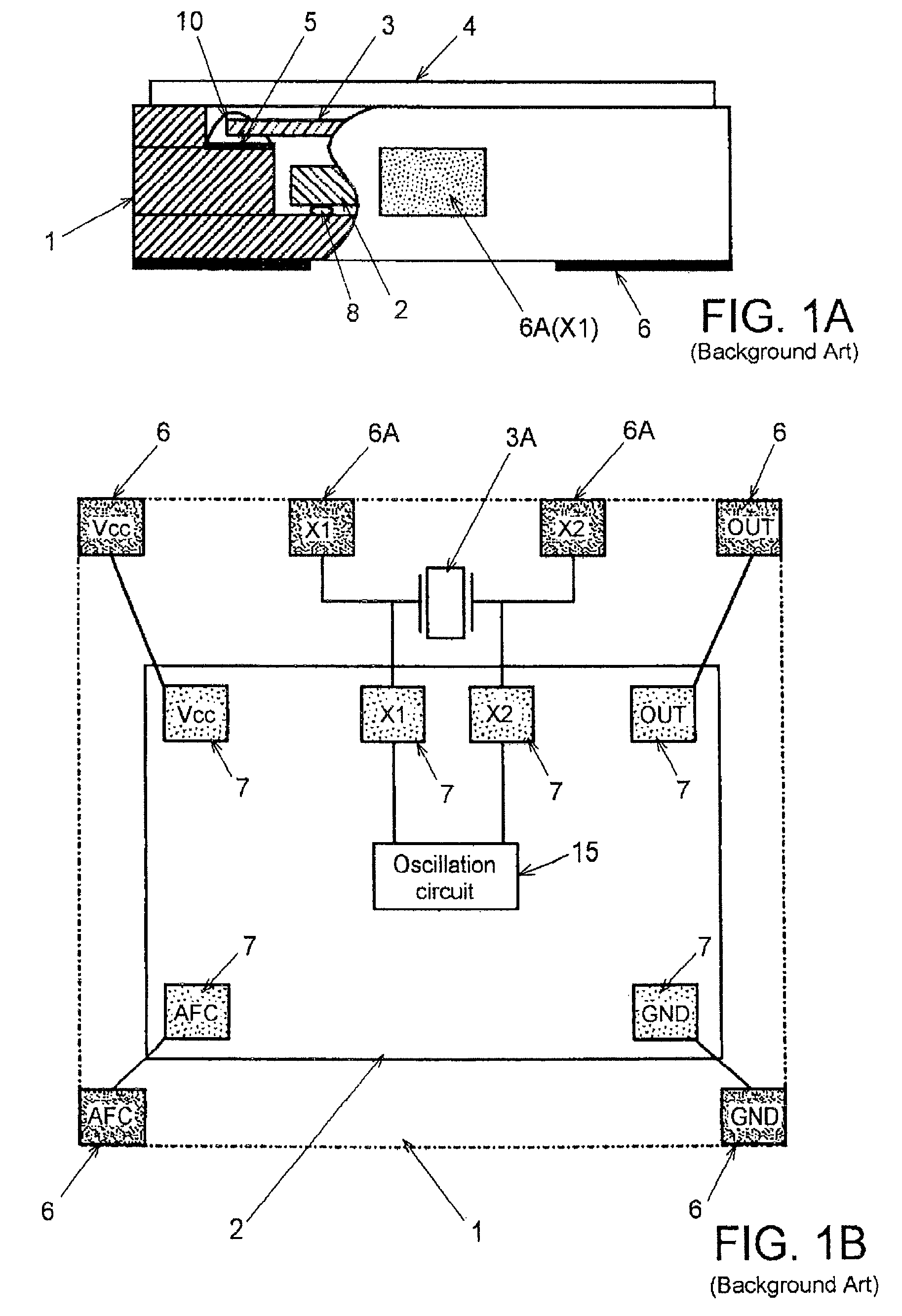
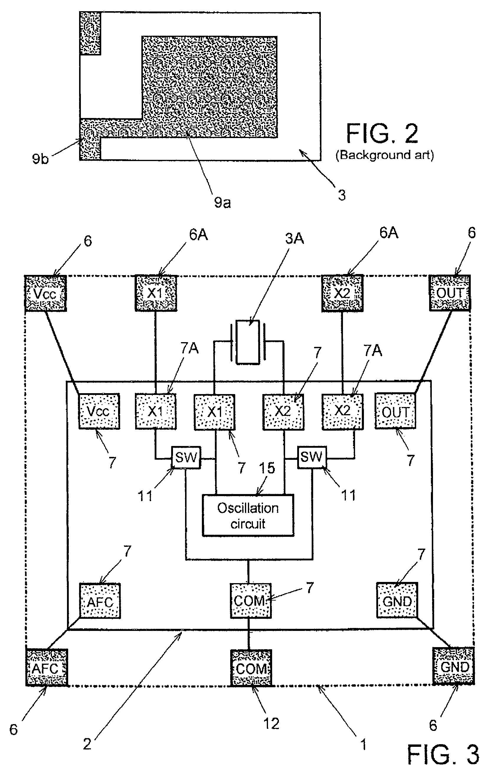
[0033]As described above, in the crystal oscillator a container body 1 having a recess is used, IC chip 2 is fixed on the inner bottom surface of the recess using ultrasonic thermo-compression as a flip-chip bonding technique, crystal blank 3 is fixed on the upper surface of the step portion formed in the inner side wall of the recess, and the recess is closed by metal cover 4. IC chip 2 and crystal blank 3 are encapsulated in the recess. As crystal blank 3, what is shown in FIG. 2 can be used. As shown in FIG. 1A, crystal blank 3 is held in the recess by fixing both sides of an end of crystal blank 3 to which lead-out electrodes 9b are extended to a pair of holding electrodes 5 formed on the upper surface of the step portion of the recess using electrically conducting adhesive 10. On the outer side surface of container body 1, a pair of inspection terminals 6A(X1), 6A(X2) used for inspecting the characteristics crystal blank 3 are provided.

[0034]IC chip 2 is further provided with ...

second embodiment

[0037]Next, a crystal oscillator according to the present invention will be described referring to FIG. 4. In FIG. 4, the same reference numerals are given to the components same as those shown in FIG. 3.

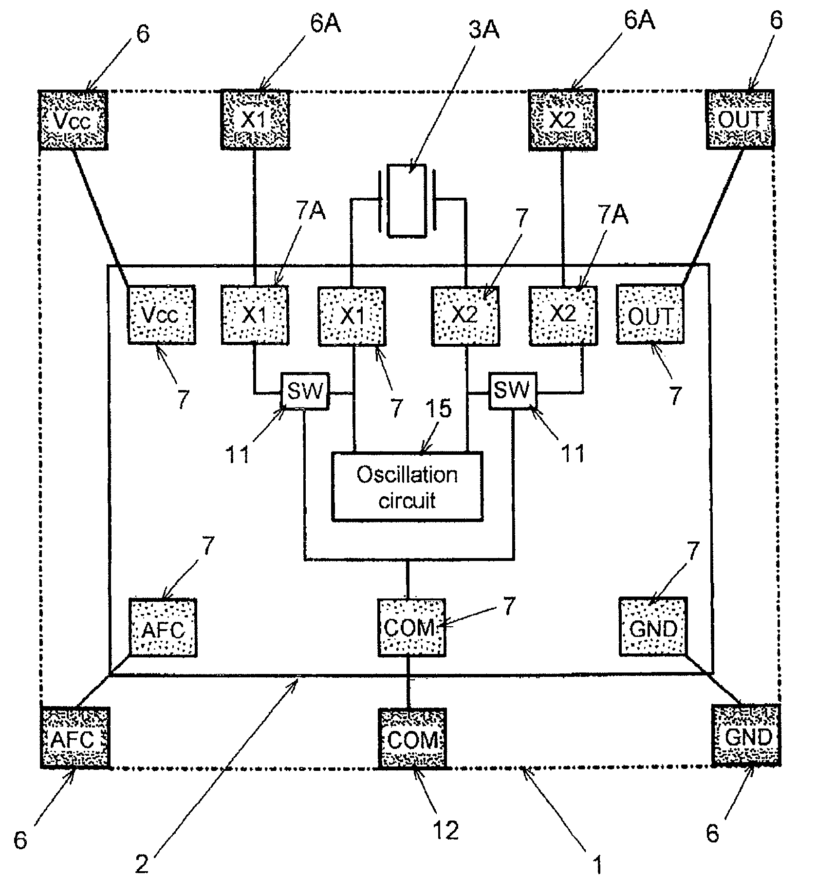
[0038]The crystal oscillator according to the second embodiment is a crystal oscillator wherein electronic switch (SW) 13 and inverter 14 are further provided in IC chip 2 in the crystal oscillator according to the first embodiment. Electronic switch 13 is provided between crystal IC terminals 7(X1), 7(X2) and oscillation circuit 15, and switchably connects crystal IC terminals 7(X1), 7(X2) to oscillation circuit 15. To electronic switch 13, the selecting signal whose logic is inverted by inverter 14 are supplied. Therefore, in the crystal oscillator, when the selecting signal supplied to communication terminal 12(COM) is “1”, electronic switch 11 is conductive and electronic switch 13 is disconnected. When the supplied selecting signal is “0”, electronic switch 11 is disconnected, ...

third embodiment

[0042]Next, a crystal oscillator according to the present invention will be described referring to FIG. 5. In FIG. 5, the same reference numerals are given to the same components as those in FIGS. 3 and 4.

[0043]The crystal oscillator according to the third embodiment is a crystal oscillator same as the crystal oscillator according to the second embodiment from which inverters 14 in IC chip 2 are removed. Instead, IC chip 2 is further provided with control IC terminal 7(COM) for each electronic switch 13. Control IC terminals 7(COM) are used for supplying selecting signals to corresponding electronic switches 13. Corresponding to these newly provided IC terminals 7(COM) for controlling, separate communication terminals 12(COM) are provided in container body 1. Specifically, in the crystal oscillator, by suitably selecting the selecting signals supplied to electronic switches 11, 13 respectively, the conducting states of electronic switches 11, 13 can be independently controlled.

[0044...


PUM


Abstract

A surface-mount type crystal oscillator comprises: a crystal blank; an IC chip on which at least an oscillation circuit using the crystal blank is integrated; a container that accommodates the crystal blank and the IC chip; a pair of inspection terminals provided on an outer surface of the container and electrically connected to the crystal blank, and used for inspecting characteristics of the crystal blank; a communication terminal provided on the outer surface of the container; and first switching means for switchably and electrically connecting and disconnecting the inspection terminals to and from the crystal blank in accordance with a selecting signal supplied from the communication terminal.

Description

BACKGROUND OF THE INVENTION[0001]1. Field of the Invention[0002]The present invention relates to a quartz crystal oscillator for surface mounting, and more specifically to a crystal oscillator having an inspection terminal, which is used for inspecting the characteristics of a quartz crystal blank, on the outer surface of the container body.[0003]2. Description of the Related Arts[0004]A surface-mount type quartz crystal oscillator wherein a quartz crystal blank and an IC (integrated circuit) chip equipped with an oscillation circuit using the crystal blank are accommodated in a container body for surface mounting is widely built in portable electronic devices represented by mobile phones as a reference source for frequency and time because of small size and light weight thereof. Examples of such surface-mount type crystal oscillators include a crystal oscillator wherein a container body having a recess formed on one of principal surfaces is used, and an IC chip and a crystal blank ...

Claims


Application Information

Patent Timeline
Patent Type & Authority Patents(United States)
IPC IPC(8): H03B1/00
CPCH03B5/32H03H9/0547
Inventor YAMAKAWA, TSUTOMU
Owner NIHON DEMPA KOGYO CO LTD
Why Eureka
Try Eureka