System and method for rasterizing primitives using direct interpolation

Inactive Publication Date: 2010-08-03
S3 GRAPHICS
View PDF18 Cites 2 Cited by
  • Summary
  • Abstract
  • Description
  • Claims
  • Application Information

AI Technical Summary

Benefits of technology

[0017]The method of the present invention is generalized so that any desired value at a given point can be derived from known values at vertices. Thus the known vertices can be described in terms of their channel values, such as coordinates (for example, X, Y, U, V, Z, or any combination thereof) or parameters (for example, color values), or some combination thereof. Given the values of some known parameters at some position, such as a point intersecting a line that connects two vertices, the method of the present invention will determine, using direct (i.e., non-incremental) perspective or linear interpolation, values for unknown parameters at that position. This technique provides several advantages. Relatively low setup overhead is incurred, since vertices of primitives can be used directly, without additional complex setup computations. This results in higher primitive throughput. For example, a method of rendering a graphic primitive in accordance with an embodiment of the invention includes, deriving a channel value of a first point on a first edge of the primitive; deriving a channel value of a second point on a second edge of the primitive; and based upon the channel values of the first point and the second point, determining a channel value for an interior point located within an interior surrounded by the edges of the primitive.
[0018]In addition, this technique facilitates computation on an as-needed basis, so that any required computations for other portions of the primitive may be deferred until needed. Pixels may be generated in any convenient order, without the sequential limitations of incremental methods. The resulting flexibility increases efficiency for implementations of more advanced features or techniques. Such method

Problems solved by technology

This computation can be an expensive process.
Conventional graphics system thus encounter a tradeoff in computational load between the setup stage and the rasterization stage.
Conversely, the use of smaller primitives reduces the amount of interpolation, but necessarily involves more computational load in the setup stage due to the increased number of primitives.
Conventional graphics systems use distinct processor modules for the two stages, so that computational capacity cannot easily be shifted from one stage to the other.
Therefore, such systems are often unable to efficiently process graphics when the numb

Method used


Image

  • System and method for rasterizing primitives using direct interpolation
  • System and method for rasterizing primitives using direct interpolation
  • System and method for rasterizing primitives using direct interpolation

Examples


Embodiment Construction

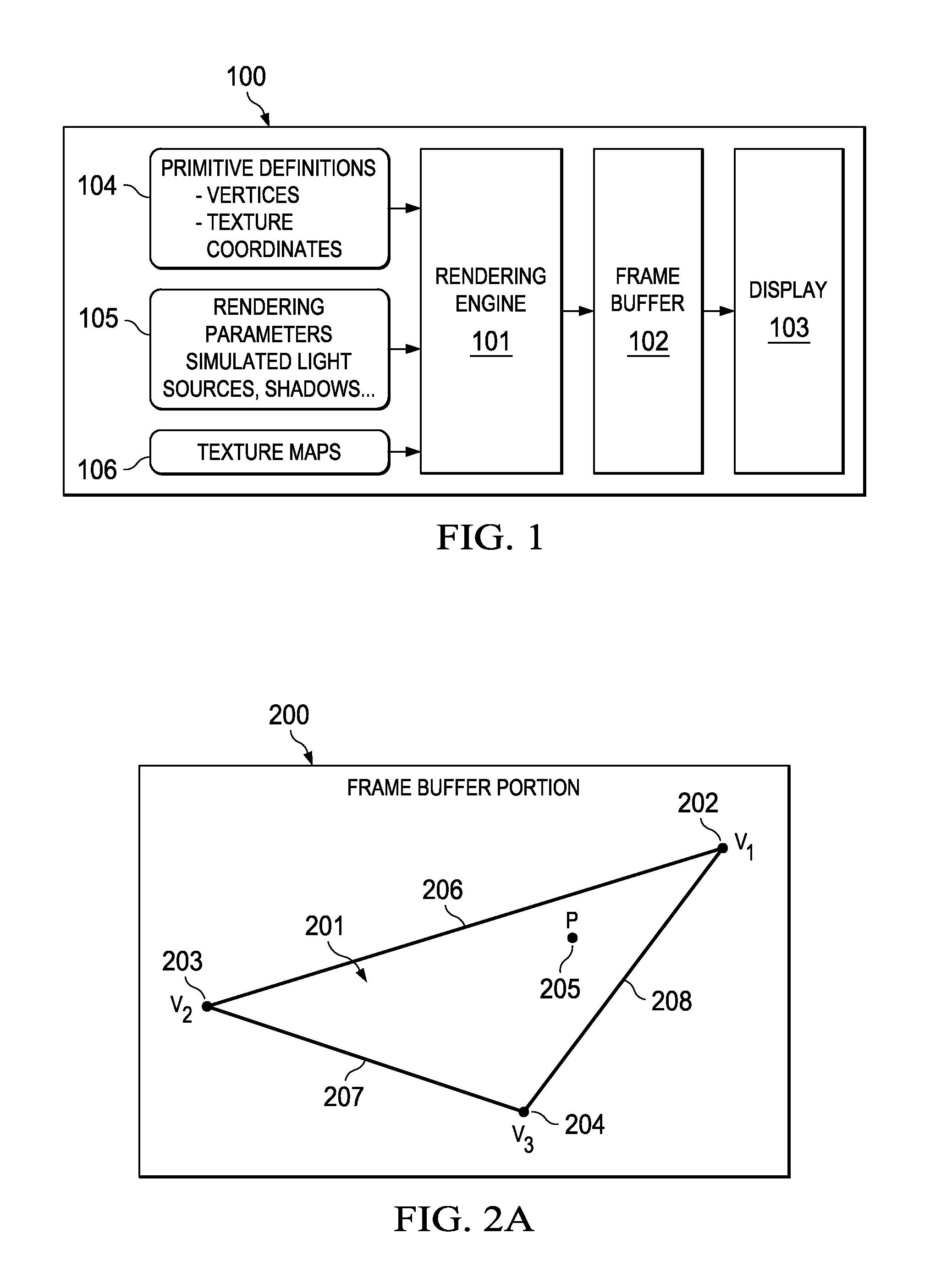
[0033]Referring now to FIG. 1, there is shown a block diagram of a graphics system for practicing the present invention. System 100 is typically implemented on a computer system such as a personal computer having an Intel Pentium™ processor and running the Windows™ 95 operating system from Microsoft Corporation. However, those of ordinary skill in the art will realize that the practice or implementation of the present invention is not limited to the system disclosed in FIG. 1. Rendering engine 101 contains software and hardware for rendering primitives into frame buffer 102. Frame buffer 102 is typically implemented in an area of random-access memory (RAM) that may be optimized for video data storage. Individual memory locations in frame buffer 102 correspond to defined points on display 103. Data from frame buffer 102 is sent to display 103 for output to the user. Display 103 is typically a cathode-ray tube, but may be based on some other form of display technology.

[0034]Rendering ...


PUM


Abstract

A system and method for rendering a graphic primitive by linear or perspective interpolation from vertex points. An interpolation engine is employed to interpolate channel values along edges of the primitive to determine values along a scan line containing a selected point. The interpolation engine is then employed to interpolate along the scan line. Processing time may further be reduced by the use of an improved adder/subtractor as a component of the interpolation engine to reduce sequential steps and improve parallelism.

Description

CROSS-REFERENCE TO RELATED APPLICATION[0001]The subject matter of this application is related to the subject matter of co-pending U.S. patent application Ser. No. 09 / 020,152 filed on Feb. 6, 1998, by Konstantine Iourcha, Andrea Nguyen, and Daniel Hung, entitled “FAST ADDER / SUBTRACTOR FOR SIGNED FLOATING POINT NUMBERS”, which is fully incorporated herein by reference. This application claims priority to U.S. Provisional Application Ser. No. 60 / 095,995 filed on Aug. 10, 1998, by Konstantine Iourcha et al., entitled “RATIO ENGINE FOR GRAPHIC INTERPOLATION”, which is fully incorporated herein by reference.BACKGROUND OF THE INVENTION[0002]1. Field of the Invention[0003]The present invention relates generally to rendering graphics system, and more particularly to texture mapping in graphics systems.[0004]2. Description of Background Art[0005]In many graphics applications, three-dimensional images are displayed on a computer screen by rendering a large number of graphic primitives, which a...

Claims


Application Information

Patent Timeline
IPC IPC(8): G06T11/20G09G5/00
CPCG06T11/40G06T15/80
Inventor IOURCHA, KONSTANTINE I.CHIN, CHUNG-KUANGHONG, ZHOU
Owner S3 GRAPHICS
Why Eureka
Try Eureka