Electronic switching device, in particular circuit-breaker and associated operating method

a technology of electronic switching device and operating method, which is applied in the direction of circuit-breaking switch, emergency protective arrangement for limiting excess voltage/current, pulse technique, etc., and can solve problems such as device destruction

Inactive Publication Date: 2010-08-03
SIEMENS AG
View PDF19 Cites 45 Cited by
  • Summary
  • Abstract
  • Description
  • Claims
  • Application Information

AI Technical Summary

Benefits of technology

[0053]At least one embodiment of the invention includes the specific combination of an SiC-JFET with a MOSFET embodied as a so-called SPM (Smart Power MOSFET) and a thyristor with associated

Problems solved by technology

The electronic switching devices used in practice are based on thyristor technology and are only suitable for operational switching or overload

Method used


Image

  • Electronic switching device, in particular circuit-breaker and associated operating method
  • Electronic switching device, in particular circuit-breaker and associated operating method
  • Electronic switching device, in particular circuit-breaker and associated operating method

Examples


Embodiment Construction

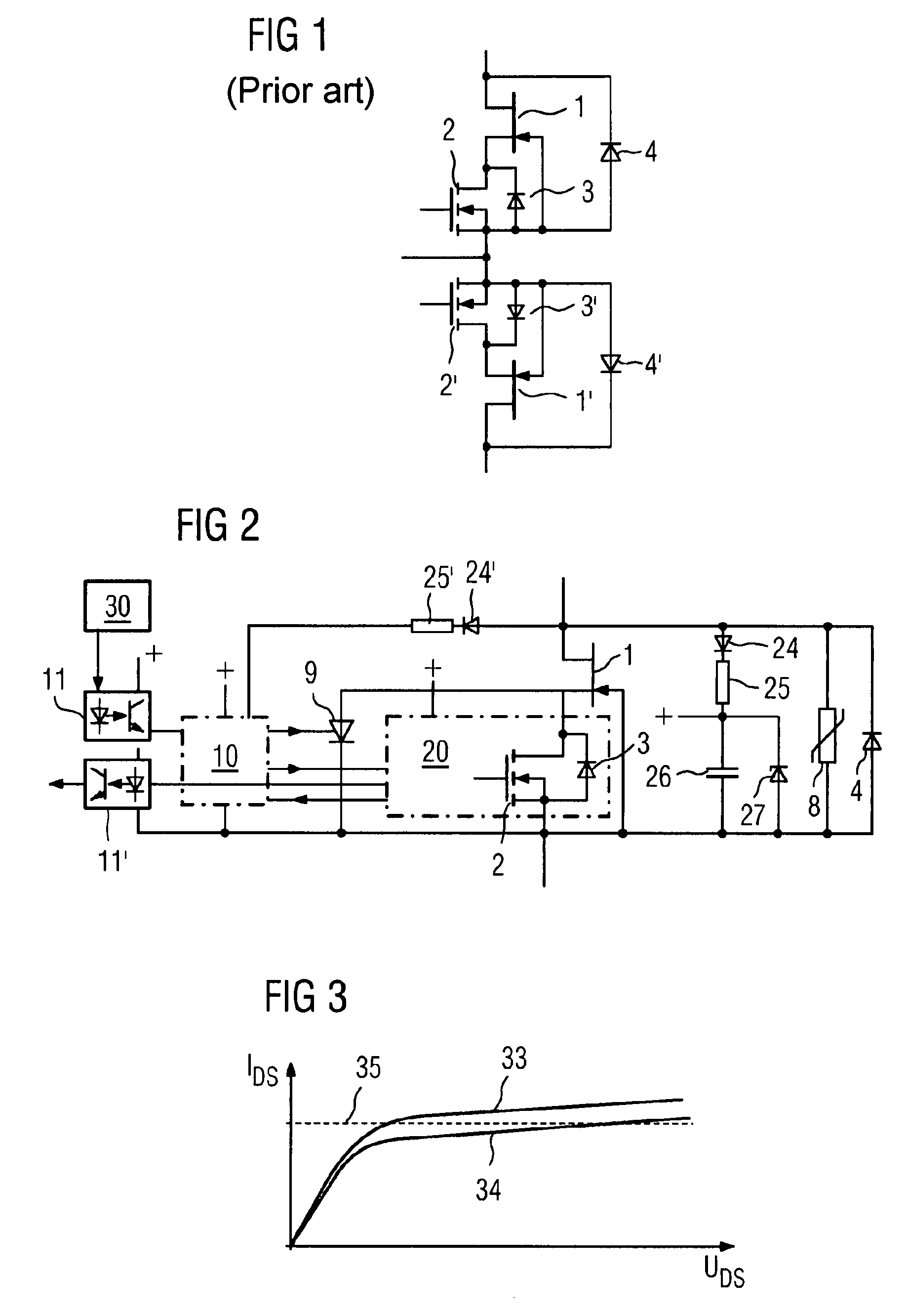
[0062]FIG. 1 shows an antiserial cascode circuit according to the prior art. It includes two SiCJFETs 1 and 1′, each of which is connected to an Si-MOSFET 2 or 2′. Thus, the elements 1, 2 and 1′, 2′ produce an antiserial series-connected arrangement. A blocking diode 3 or 3′ is present in each case. The diode 4 or 4′ handles the current in the reverse direction.

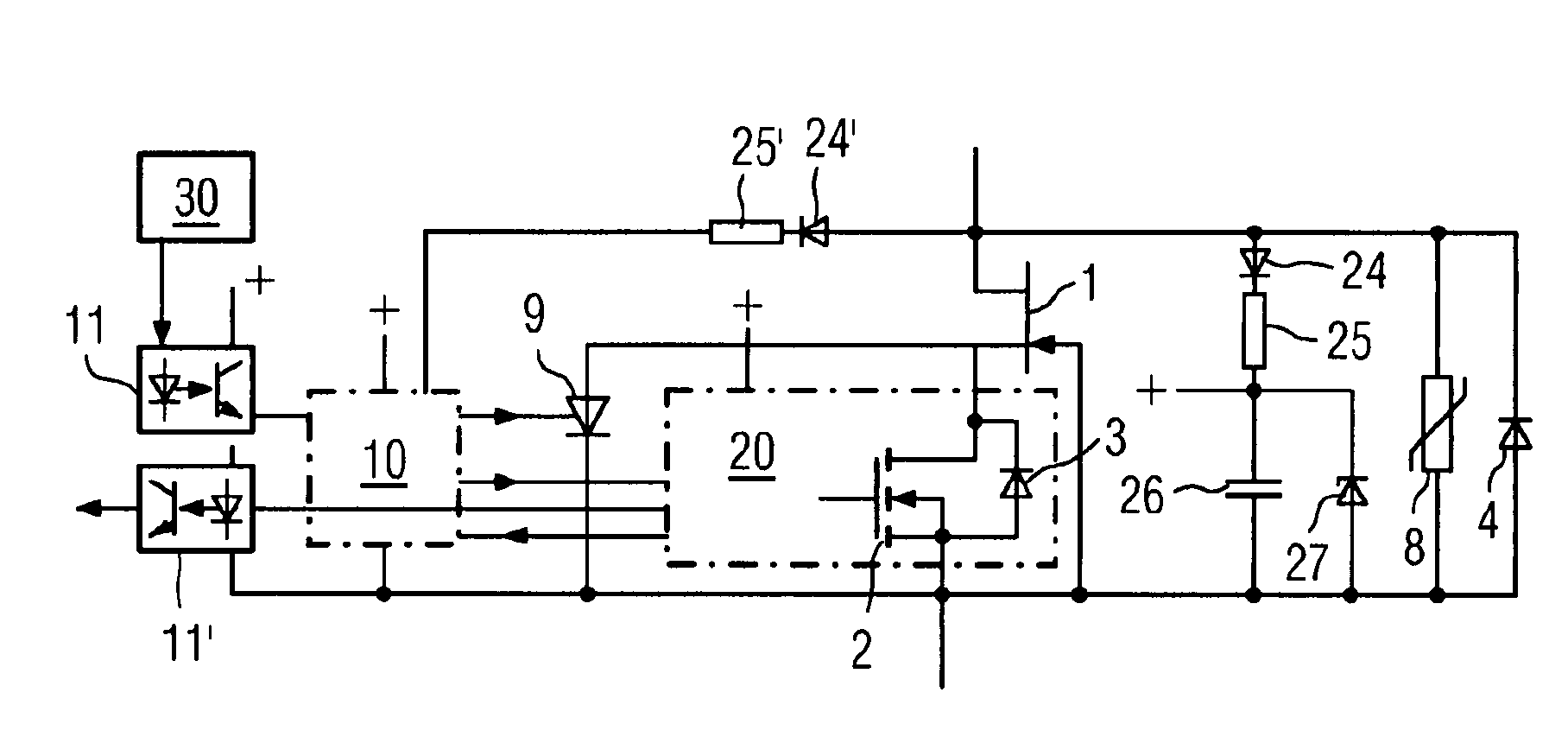
[0063]In FIG. 2 a thyristor-based soft starter control section with overload protection function is combined with a so-called SPM (Smart Power MOSFET). In this case only half of the circuit is shown in FIG. 2. The same circuit must be connected antiserially in series as shown in FIG. 1, in order in particular to produce an alternating current switch.

[0064]Specifically reference symbol 1 in FIG. 2 again refers to the SiC-JFET from FIG. 1. The overall SPM is labeled 20. Furthermore there is a thyristor 9 with an associated control section 30. The interaction of SPM 20 and thyristor 9 is guaranteed by a logic chip 10. Functions ...


PUM


Abstract

An anti-serial cascade circuit including two silicon carbide JFETs and two silicon MOSFETs is known. Disclosed is a combination of a JFET, a smart power MOSFET SPM and a thyristor with an associated trigger circuit, which is connected in parallel to the SPM. According to an embodiment of the invention, a logic circuit co-ordinates the functional sequence.

Description

PRIORITY STATEMENT[0001]This application is the national phase under 35 U.S.C. §371 of PCT International Application No. PCT / EP2005 / 054643 which has an International filing date of Sep. 19, 2005, which designated the United States of America and which claims priority on German Patent Application number 10 2004 046 823.0 filed Sep. 27, 2004, the entire contents of which are hereby incorporated herein by reference.FIELD[0002]Embodiments of the invention generally relate to an electronic switching device, in particular a circuit breaker. In addition, embodiments of the invention also generally relate to the associated method of operation of the switching device.BACKGROUND[0003]Electromechanical and electronic switching devices are known to be used for switching alternating current. With electromechanical switching devices a distinction is made between switching devices for operational switching (“contactors”) and for short circuit switching (“circuit breakers”). Depending on the protec...

Claims


Application Information

Patent Timeline
IPC IPC(8): H02H3/08H03K17/00H03K17/0814H03K17/567
CPCH03K17/08148H03K17/567
Inventor MAIER, REINHARDRUPP, JURGENSCHROCK, MICHAEL
Owner SIEMENS AG
Why Eureka
Try Eureka