Method of imaging subsurface formations using a virtual source array

a virtual source array and subsurface technology, applied in the field of controlled source electromagnetic surveys, can solve the problems of unfocused excitation, large number of electrode wires required in the concentric electrode ring, and the length of electrode wires that are required, and achieve the effect of reducing the number of electrode wires

Active Publication Date: 2010-08-03
EXXONMOBIL UPSTREAM RES CO
View PDF15 Cites 6 Cited by
  • Summary
  • Abstract
  • Description
  • Claims
  • Application Information

AI Technical Summary

Benefits of technology

[0009]This invention relates generally to a method of simulating the signal of an electromagnetic source using one or more dipole sources. In the method a dipole source is located at an excitation location corresponding to a segment of the electromagnetic source to be simulated. The dipole source is activated, and an electromagnetic signal recorded at one or more receiver locations. This process is repeated for additional excitation locations corresponding to additional segments of the source being simulated. The data from the sequence of dipole source excitation locations is processed to determine the simulated signal of the electromagnetic source.

Problems solved by technology

Unfocused excitations are a severe disadvantage when a target-oriented survey is needed, such as when it is desirable to probe the electrical properties of a prospective formation in a location where a complex geologic background may be present.
A limitation of the Srnka method, however, is that for typical reservoir depths, which range from 500 meters to greater than 5000 meters, the total length of electrode wire that is required in the concentric electrode rings ranges from about 23.5 km to greater than 235 km.
These extreme lengths of electrode wire raise numerous operational challenges.
For example, difficulties in handling and deploying the electrode wires, and problems in ensuring accurate positioning of the wires in the desired electrode ring locations may be involved, and there is the need to avoid obstacles in the area of the desired ring locations, and the requirement that the electrodes be uniformly grounded along their lengths.
Other problems influence the economics of the survey, including the large cost of the electrode wire, some of which is likely to be damaged or lost in each survey, and the large labor and logistics costs associated with mobilization, demobilization, deployment, and recovery of the wire.
The virtual concentric ring source method nevertheless uses relatively long lengths of electrode wire and inherently retains many of the operational challenges of the R3M physical concentric ring source method.
In addition, both methods have other inherent disadvantages, in particular for certain aspects of the subsurface resistivity-imaging problem.
Specifically, both methods produce maximum responses near a pre-specified subsurface excitation focus depth (in other words, at the approximate depth of the target), but provide little differential sensitivity to features within an appreciable vertical range of that depth.
More specifically, the ability to image separately features above or below the target a distance of less than five percent of the target's depth below the surface is limited.
This limitation greatly hinders the imaging of stacked reservoirs.
In addition, amplifier saturation effects can influence data quality and hinder analysis of such data.
A third issue is that both methods produce primarily vertical subsurface currents in the region of the target.
These currents are not adequate for imaging reservoir electrical macro-anisotropy (vertical electrical isotropy), such as exists in many reservoirs due to the presence of shale interbeds.

Method used


Image

  • Method of imaging subsurface formations using a virtual source array
  • Method of imaging subsurface formations using a virtual source array
  • Method of imaging subsurface formations using a virtual source array

Examples


Embodiment Construction

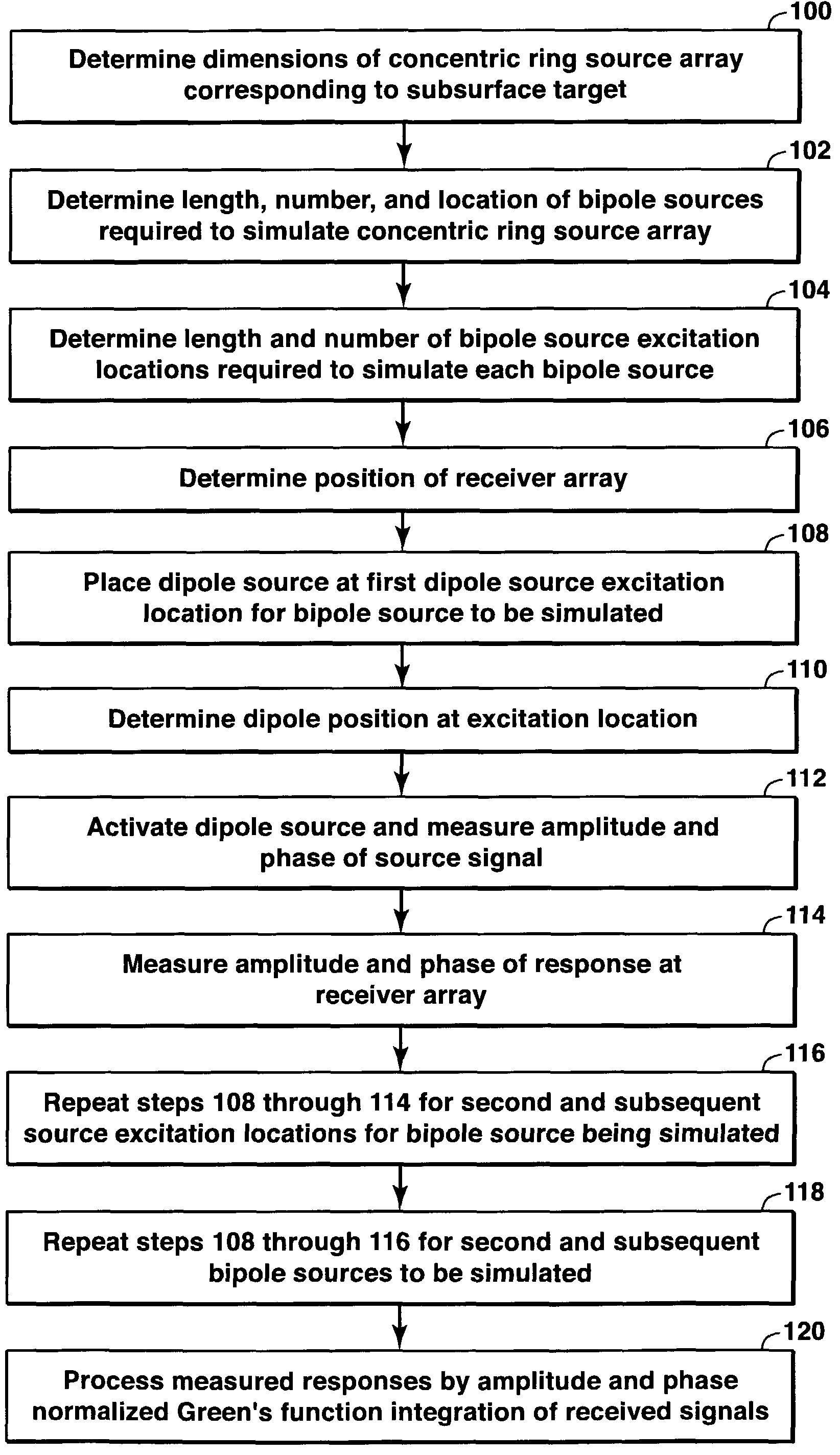
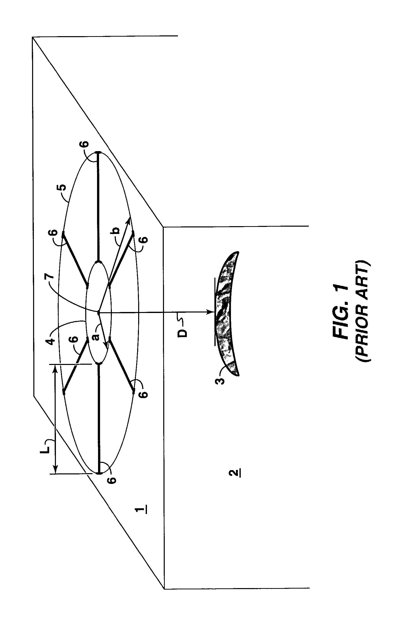
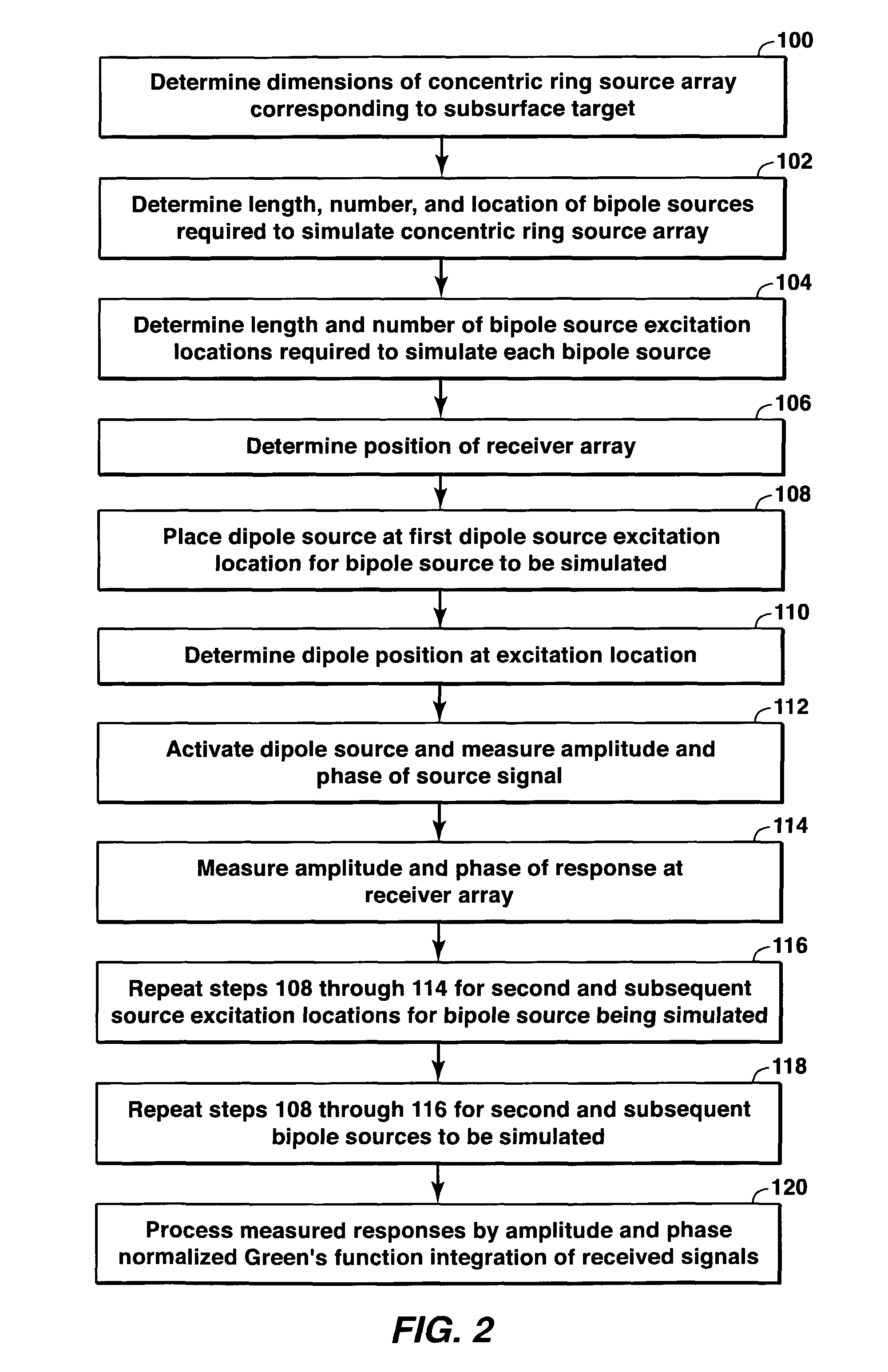
[0023]The present invention is a method of simulating the advantageous multicomponent electromagnetic response of a resistive reservoir to excitation by a concentric ring source array, or its radial bipole equivalent, with a significantly reduced amount of electrode wire. In a preferred embodiment, the method uses one or more short dipole sources, each located sequentially at source excitation locations corresponding to a location of a radial bipole to be simulated, to obtain measurement data during field surveys in the region of the subsurface target to be imaged. Phase and amplitude receiver data are synchronized with data from the source locations and summed using a Green's function integration to determine the response of the target. The method has an inherent ability to create a large number of virtual source configurations by varying the number and positions of the source excitation locations that are integrated in the receiver data, thereby facilitating much higher spatial re...


PUM


Abstract

This invention relates generally to a method of simulating the signal of an electromagnetic source using one or more dipole sources. In the method a dipole source is located at an excitation location corresponding to a segment of the electromagnetic source to be simulated. The dipole source is activated, and an electromagnetic signal recorded at one or more receiver locations. This process is repeated for additional excitation locations corresponding to additional segments of the electromagnetic source. The data from the sequence of dipole source excitation locations is processed to determine the simulated signal of the electromagnetic source.

Description

[0001]This application claims the benefit of U.S. Provisional Application No. 60 / 318,082 filed on Sep. 7, 2001.FIELD OF THE INVENTION[0002]This invention relates to the field of controlled-source electromagnetic surveys for geophysical applications. More specifically, this invention relates to a method of imaging subsurface formations using a virtual source array.BACKGROUND OF THE INVENTION[0003]Electromagnetic sources used in geophysical surveying generally produce unfocused regions of subsurface excitation. Unfocused excitations result both from the diffusive nature of low frequency electromagnetic wave propagation in the earth and from the use of relatively simple source configurations in the surveys. Unfocused excitations are a severe disadvantage when a target-oriented survey is needed, such as when it is desirable to probe the electrical properties of a prospective formation in a location where a complex geologic background may be present.[0004]To eliminate the disadvantages o...

Claims


Application Information

Patent Timeline
Patent Type & Authority Patents(United States)
IPC IPC(8): G06G7/56G01V3/12
CPCG01V3/083G01V3/12
Inventor SRNKA, LEONARD J.CARAZZONE, JAMES J.
Owner EXXONMOBIL UPSTREAM RES CO
Why Eureka
Try Eureka