
Virtual compressor operational parameter measurement and surge detection in a fuel cell system

a fuel cell and virtual compressor technology, applied in the direction of fuel cells, electrical equipment, electrochemical generators, etc., can solve the problems of compressor surge condition, compressor cannot operate at relatively high pressure ratio, relatively high manufacturing cost, etc., to reduce system back pressure, increase compressor speed, and remove surge condition

Active Publication Date: 2010-08-10
GM GLOBAL TECH OPERATIONS LLC
View PDF3 Cites 6 Cited by
  • Summary
  • Abstract
  • Description
  • Claims
  • Application Information

AI Technical Summary

Benefits of technology

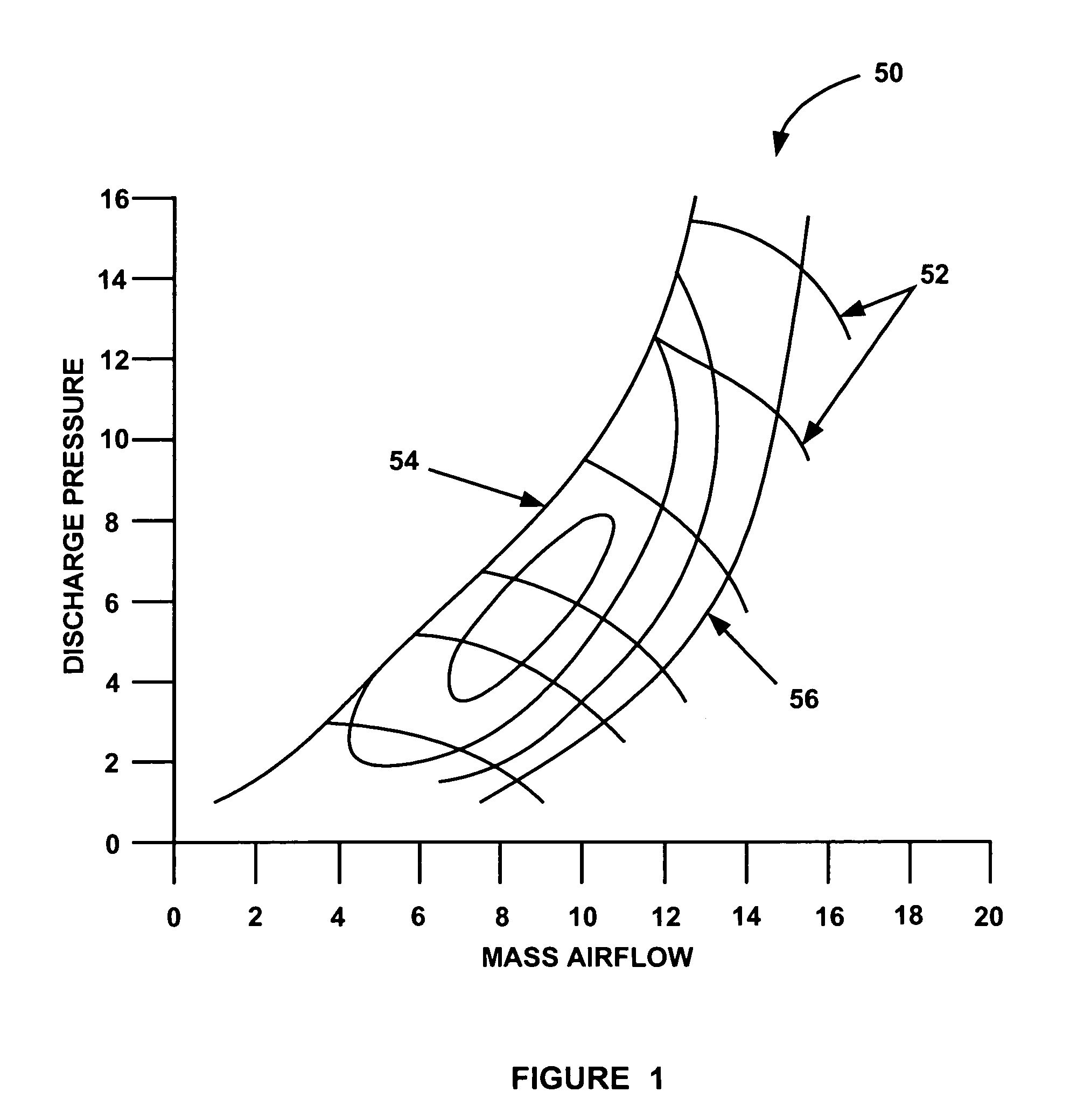
The present invention is about a fuel cell system that uses a centrifugal compressor to deliver charge air to the cathode side of a fuel cell stack. The system employs a controller that electronically maps the compressor for discharge pressure versus mass airflow to prevent compressor surge. The controller receives a signal from a mass flow meter or a pressure sensor to determine the compressor map location and takes suitable action to prevent surge, such as lowering system back pressure or increasing compressor speed. The technical effect of this invention is to improve the efficiency and reliability of fuel cell systems by preventing compressor surge and optimizing compressor operation.

Problems solved by technology

MEAs are relatively expensive to manufacture and require certain conditions for effective operation.
In other words, excessive back-pressure from the fuel cell system could cause a compressor surge condition.
The compressor cannot operate at relatively high pressure ratios that put the compressor into a surge condition because of severe oscillation of the airflow through the compressor that could damage the compressor.

Method used


Image

  • Virtual compressor operational parameter measurement and surge detection in a fuel cell system
  • Virtual compressor operational parameter measurement and surge detection in a fuel cell system
  • Virtual compressor operational parameter measurement and surge detection in a fuel cell system

Examples


Embodiment Construction

[0018]The following description of the embodiments of the invention directed to a fuel cell system employing a technique for preventing a compressor surge condition is merely exemplary in nature, and is in no way intended to limit the invention or its applications or uses.

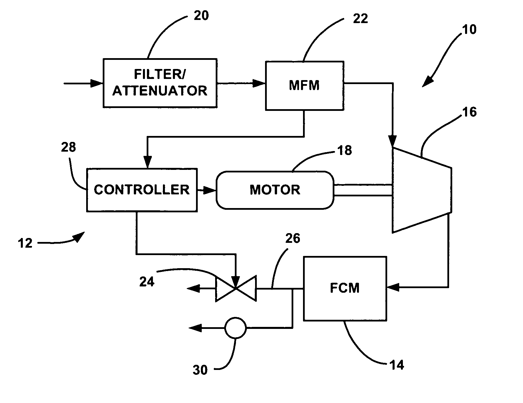
[0019]FIG. 2 is a plan view of a fuel cell system 10 including an air delivery sub-system 12 and a fuel cell module (FCM) 14 having a fuel cell stack of the type discussed above. The fuel cell system 10 can be used for any suitable application, such as on a vehicle or a distributed generation power system.

[0020]The sub-system 12 includes a turbo-machine compressor 16 that provides charge air to the cathode side of the FCM 14. The compressor 16 can be any suitable turbo-machine type compressor, such as a centrifugal, radial, axial, mixed flow, etc., compressor. This type of compressor is desirable in the system 10 because it is low cost and low weight, and operates with low noise as compared to the positive displace...


PUM

PropertyMeasurementUnit
mass flow meteraaaaaaaaaa
speedaaaaaaaaaa
pressureaaaaaaaaaa

Abstract

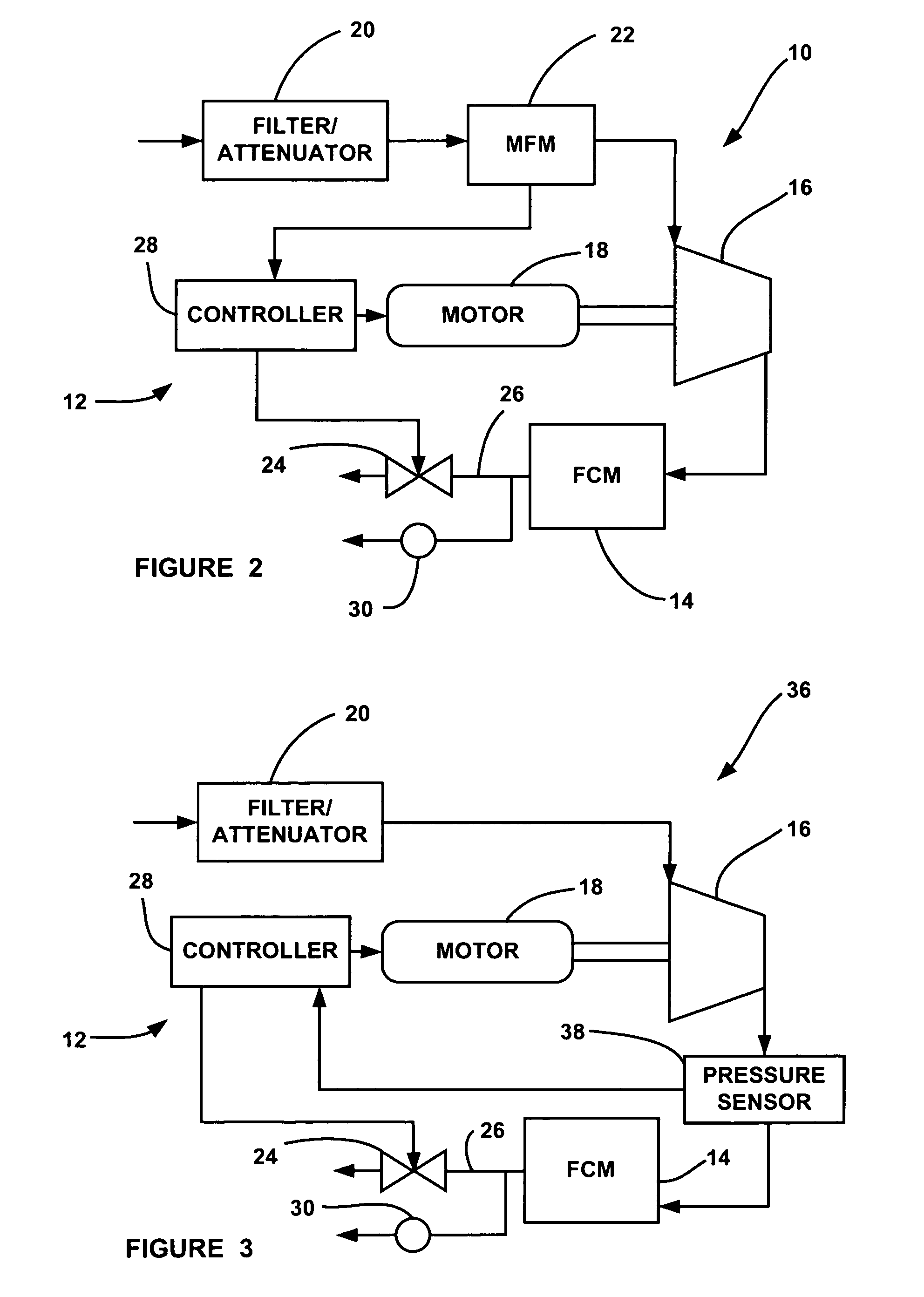
A fuel cell system that employs surge prevention by electronically mapping the compressor for discharge pressure versus mass airflow. In one embodiment, the fuel cell system employs a mass flow meter that measures the airflow to the compressor. A controller receives a signal from the mass flow meter indicative of the flow rate of the charge airflow to the compressor, and determines the outlet pressure and temperature of the compressor from the compressor speed and the measured airflow. This gives the compressor map location at which the compressor is operating. In another embodiment, the fuel cell system employs a pressure sensor that measures the output pressure of the compressor, and provides a pressure signal to the controller. The controller determines the mass airflow to the compressor to determine the compressor map location.

Description

BACKGROUND OF THE INVENTION[0001]1. Field of the Invention[0002]This invention relates generally to an air delivery sub-system for a fuel cell system and, more particularly, to an air delivery sub-system for a fuel cell system, where the air delivery sub-system uses a compressor map to control the compressor speed to prevent the compressor from approaching a surge condition.[0003]2. Discussion of the Related Art[0004]Hydrogen is a very attractive fuel because it is clean and can be used to efficiently produce electricity in a fuel cell. The automotive industry expends significant resources in the development of hydrogen fuel cells as a source of power for vehicles. Such vehicles would be more efficient and generate fewer emissions than today's vehicles employing internal combustion engines.[0005]A hydrogen fuel cell is an electro-chemical device that includes an anode and a cathode with an electrolyte therebetween. The anode receives hydrogen gas and the cathode receives oxygen or a...

Claims


Application Information

Patent Timeline
Patent Type & Authority Patents(United States)
IPC IPC(8): H01M8/04
CPCH01M8/04089Y02E60/50
Inventor POSPICHAL, PETERRAINVILLE, JOSEPH D.
Owner GM GLOBAL TECH OPERATIONS LLC
Learn More