
Barrel system for a paintball marker

a barrel system and paintball marker technology, applied in the field of barrel systems, can solve the problems of high friction force of paintball, adversely affecting the aim of the player, and abrupt step-wise tapering, etc., to achieve the effect of maximizing speed and directional stability, reducing friction, and improving accuracy

Inactive Publication Date: 2010-08-17
SLY
View PDF29 Cites 15 Cited by
  • Summary
  • Abstract
  • Description
  • Claims
  • Application Information

AI Technical Summary

Benefits of technology

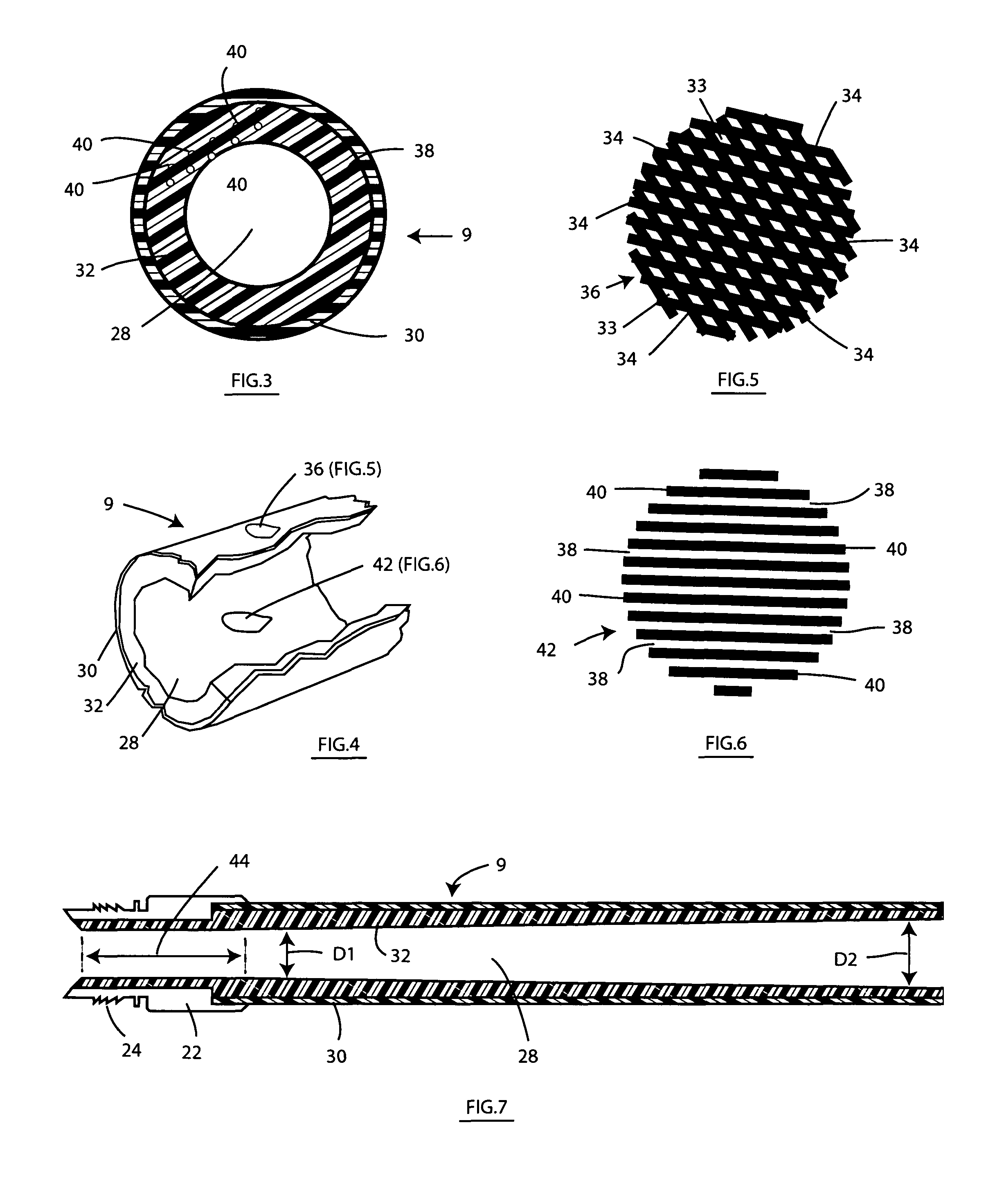
"The patent describes an interchangeable barrel system for a paintball marker that can be easily connected and disconnected. The barrel system includes a metallic breach and a composite front made up of a thin layer of unidirectional fibers embedded in a resin. The composite front reduces friction, improves accuracy, and allows for easy cleaning. The front is tapered to increase the diameter of the hollow bore, which reduces turbulence and drag. The outer layer is made of woven fibers that provide a lightweight reinforcement and enhance the look and feel of the barrel system. The technical effects of this invention include improved performance and ease of use for paintball markers."

Problems solved by technology

As a consequence of the metallic barrel system, a paintball is subjected to high friction forces, particularly as it travels down a one-piece barrel system.
Moreover, the metallic barrel system may contain grooves or other imperfections that are introduced during machining which can sometimes impart a spin to the paintball that may alter its direction and adversely affect the aim of the player.
However, such a step-wise taper is very abrupt for a rapidly moving paintball.
Thus, the paintball may experience turbulence as it exits the front of the barrel system giving the player less accuracy and control.
The texture of the mesh liner may cause the fragile gelatin capsule around the paintball to rupture and thereby allow paint to be spilled along the bore.
The texture of the mesh liner also makes it difficult to clean the breach and remove the paint from the bore thereof.

Method used


Image

  • Barrel system for a paintball marker
  • Barrel system for a paintball marker
  • Barrel system for a paintball marker

Examples


Embodiment Construction

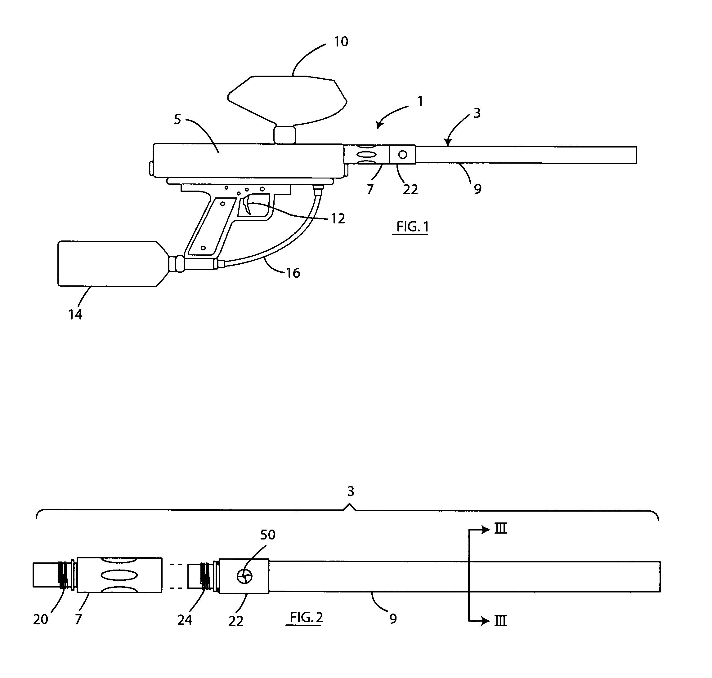
[0021]An improved barrel system 3 for a paintball marker 1 according to a preferred embodiment of this invention is described while referring initially to FIGS. 1 and 2 of the drawings. FIG. 1 shows the barrel system 3 removably connected to a body 5. FIG. 2 shows the barrel system 3 removed from the body 5. In this regard, the barrel system 3 of paintball marker 1 includes a hollow breach 7 located at the rear end thereof and a hollow front or tip 9 located at the opposite end and detached from the breach 7.

[0022]Like conventional paintball markers, the paintball marker 1 of FIG. 1 includes a hopper 10 into which a supply of paintballs (not shown) is loaded so as to be dispensed, under pressure, via the bore of the barrel system 3. Paintballs from the hopper 10 are delivered into the body 5 to be propelled through the barrel system 3 when a trigger 12 is activated by a player. To this end, a propellant tank 14 that is filled with a source of gas under pressure (e.g., typically comp...


PUM


Abstract

A barrel system for a paintball marker including a breach removably connected to the paintball marker and a composite front detachably connected to the breach. The composite front of the barrel system includes a hollow bore through which a paintball is propelled, a non-metallic inner layer surrounding the bore, and a non-metallic outer layer surrounding the inner layer. The non-metallic inner layer is preferably manufactured from a plurality of unidirectional graphite fibers embedded within an epoxy resin. The non-metallic outer layer is preferably manufactured from a plurality of graphite fibers that are woven together and embedded with an epoxy resin for surrounding and reinforcing the inner layer. The non-metallic inner layer of the composite front is smoothly and continuously tapered to cause the hollow bore to be tapered from a relatively narrow diameter to a relatively wide diameter in the direction of travel of the paintball.

Description

BACKGROUND OF THE INVENTION[0001]1. Field of the Invention[0002]This invention relates to a barrel system to be detachably connected to a paintball marker wherein the front or tip of the barrel system includes a taper and is manufactured with a plurality of unidirectional and / or woven (e.g., graphite) fibers embedded within an (e.g., epoxy) resin.[0003]2. Background Art[0004]The game of paintball is growing in popularity. Participants use pressurized gas paintball markers to propel paintballs down a barrel system and towards a target or each other. Because paintballs come in various sizes and shapes, and because paintballs are susceptible to the effects of temperature, humidity, and the like, it is known for a paintball marker to have either a continuous one-piece barrel system or a two-piece barrel system including an interchangeable breach that is mated to an interchangeable front to account for the different characteristics of the paintballs and / or to change the overall length of...

Claims


Application Information

Patent Timeline
Patent Type & Authority Patents(United States)
IPC IPC(8): F41A21/02F41B11/00
CPCF41A21/02F41B11/00
Inventor ANDERSON, KENNETH K.
Owner SLY
Learn More