

Fixed difference, dual beam laser Doppler velocimetry
a laser and velocity measurement technology, applied in the field of laser doppler velocity measurement, can solve the problems of requiring extreme mechanical stability of the laser oscillator, requiring time for light to travel from the transmitter, and requiring a stable local oscillator frequency
- Summary
- Abstract
- Description
- Claims
- Application Information
AI Technical Summary
Problems solved by technology
Method used
Image

Examples
case 1
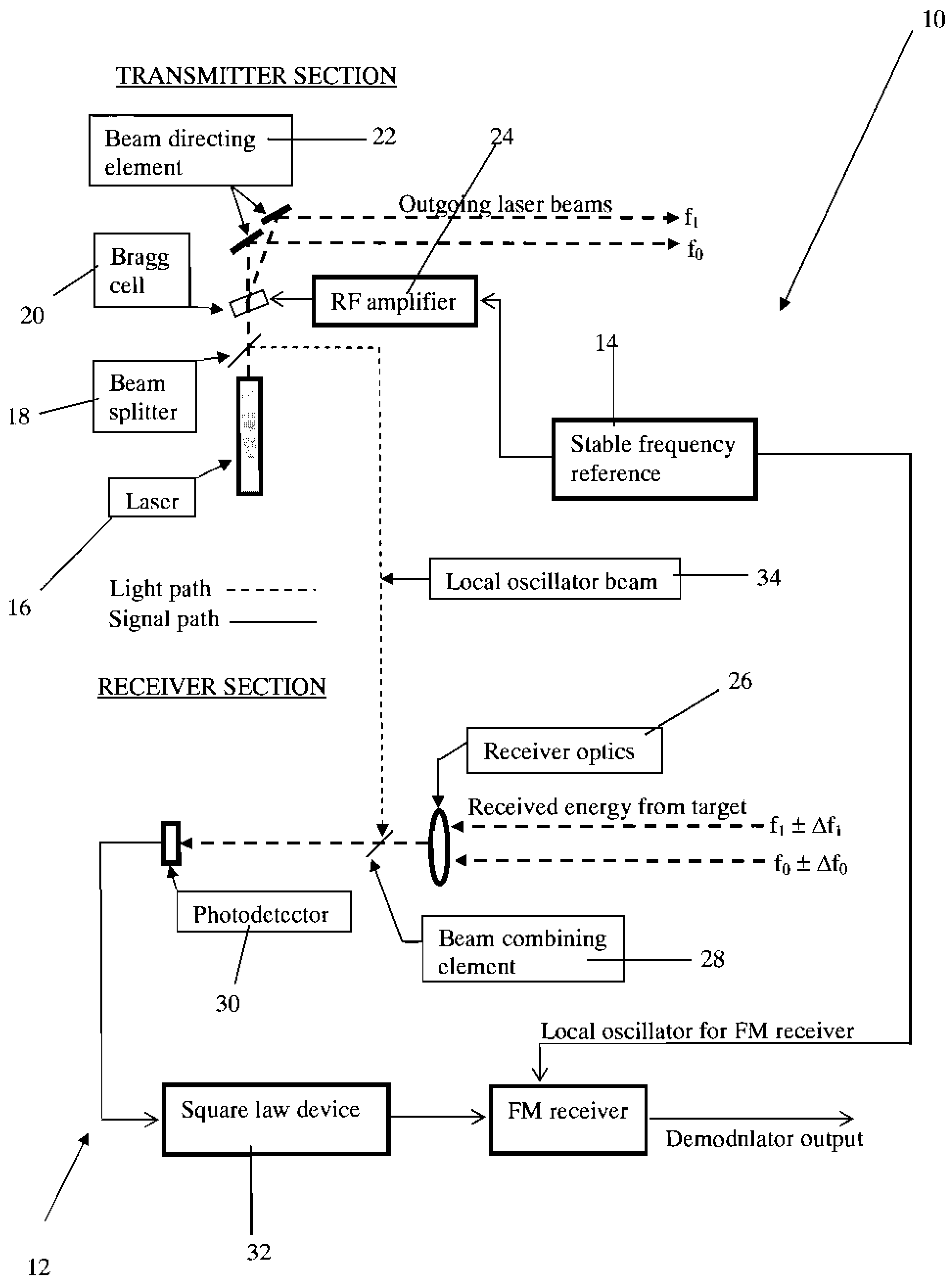
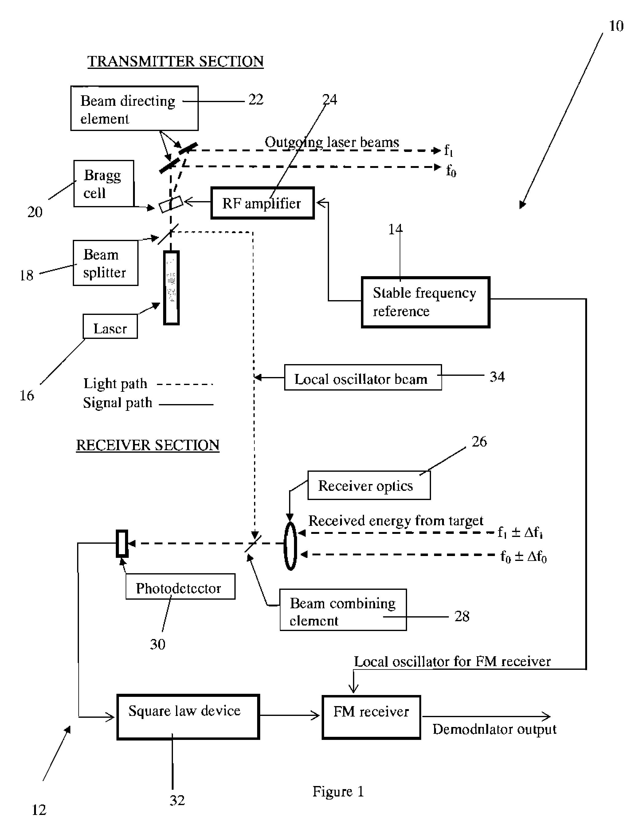
Detection
[0083]In this case, the photodetector interacts with the two light beams to generate the square of the sum of the two beams, i.e., (cos 2πf0t+cos 2πf1t)2. This produces three independent terms consisting of the squares of the individual sinusoids and the cross-product term. The summed frequencies are in the optical frequency range. Therefore they do not produce an electrical output. The squared terms generate a double frequency component and a zero frequency component. The cross-product term generates the difference frequency, (f1−f0), which is equal to fa, the desired signal.
[0084]This signal is sufficient to be processed by the FM receiver, if it is strong enough to overcome the thermal noise of the photodetector and the rest of the electronic circuitry.
case 2
dyne Detection
[0085]The objection one could make to Case 1 is that a much weaker signal, limited only by photon noise, could be received if heterodyne detection is used. This significantly reduces the laser power, or the size of the collecting optics, needed for a given application. The argument is then made that this can only be done with a stable laser local oscillator.
[0086]It is now shown that when the fixed difference, dual beam technique is implemented, the frequency of the laser LO does not need to be precisely known. However, the LO frequency must be constrained within the design limits of the electronic circuitry that follows the photodetector. This allows for a reasonable amount of mode hopping within the laser.
[0087]Let fLO be the instantaneous frequency of the laser LO beam on the photodetector. This mixes with the two return signals, generating the following operation:
(cos 2πf0t+cos 2πf1t+Acos 2πfLOt)2
which generates six independent products. The only ones of interest ...
PUM
 Abstract
Description
Claims
Application Information