Extrusion head with planarized edge surface

a planarized edge surface and extrusion head technology, applied in the field of micro extrusion systems and methods, can solve the problems of large variation in flow impedance of multiple orifice systems, unavoidable and unpredictable shape changes of extrusion heads, and inability to meet the requirements of micro extrusion structures, etc., to achieve highly precise planarized edge surfaces, facilitate the trimming of edge surfaces, and facilitate the effect of edge surface trimming

Inactive Publication Date: 2010-08-24
SOLARWORLD INNOVATIONS
View PDF204 Cites 49 Cited by
  • Summary
  • Abstract
  • Description
  • Claims
  • Application Information

AI Technical Summary

Benefits of technology

[0007]The present invention is directed to an extrusion head for a micro extrusion apparatus that utilizes one or more precisely formed reference surfaces to facilitate the trimming of an edge surface of the extrusion head in order to provide a desired (e.g., planar) shape. The extrusion head is made up of sheets (e.g., metal plates) that are bonded together using high pressure bonding techniques to form a composite structure. Central sheets of the composite structure are etched prior to the bonding process to include inlet ports and cavities that form fluidic channels for extruding materials through associated outlet orifices onto the target substrate. In accordance with the present invention, the reference surfaces are etched into one or more of these central sheets using the same mask(s) that are used to form the cavities / inlet ports. After the bonding process and an optional dicing process, side edges of the various sheets form an edge surface of the composite extrusion head, where the outlet portions of the cavities form spaced-apart outlet orifices in the edge surface, and the reference surfaces are disposed in spaced apart indentations (notches) that are also defined in the edge surface. Due to the assembly process, the edge surface of the extrusion head is initially non-planar, and requires a subsequent trimming process to achieve the desired extrusion head performance. In accordance with an aspect of the present invention, trimming of the edge surface is performed using the reference surfaces as a precise guide; that is, material is removed (e.g., by grinding or other abrasion process) until each of the reference surfaces is located a predetermined distance from the edge surface. By defining and using the reference surfaces in this manner, extrusion heads are produced, for example, with precisely planar edge surfaces, whereby all of the outlet orifices defined on the edge surface can be reliably uniformly positioned over a target substrate during a subsequent micro extrusion process to avoid production problems associated with conventional methods.
[0008]In accordance with an embodiment of the present invention, a micro extrusion apparatus is used for forming closely spaced high-aspect ratio gridline structures on a substrate surface in which the gridlines are co-extruded with a sacrificial material onto the substrate surface such that the high-aspect ratio gridline is supported between two sacrificial material portions (the sacrificial portions are subsequently removed). The formation of such co-extruded structures requires the compression of the gridline material between the two sacrificial material portions, which requires the use of a relatively wide three-part fluidic channel feeding a relatively narrow outlet orifice in a manner that compresses the gridline material between the two sacrificial material portions. Due to the width of the three-channel cavity, the spacing between adjacent outlet orifices on each head (and, hence, the pitch of the extruded gridlines) is larger than the size of each outlet orifice (i.e., a relatively large space is provided between adjacent outlet orifices on the co-extrusion head). According to the present invention, the relatively wide spacing between adjacent outlet orifices is utilized to provide a series of reference surfaces such that each outlet orifice is located between two associated reference surfaces on the edge surface of the co-extrusion head. The multiple, relatively uniformly spaced reference surfaces, each precisely etched to define a straight line that is parallel to the desired planar edge surface, facilitate precise planarization of the edge surface.
[0009]In accordance with another embodiment of the present invention, multiple co-extrusion heads are manufactured together by etching rows of fluidic channels and feed channels on a set of sheets, where each row of etched features corresponds to an associated co-extrusion head of the multiple heads. The etched sheets are bonded to form a multi-head block, which is then diced to form individual co-extrusion heads. In this embodiment, the outlet portion of each cavity (i.e., fluidic channel) includes a T-shaped opening, where the fluidic channel forms the central vertical portion of the T-shaped opening, and the reference surfaces are formed at lower ends of the bars that extend downward from the upper horizontal bar of the T-shaped opening. The T-shaped openings associated with the multiple fluidic channels of the extrusion head are arranged such that the upper horizontal bars of the T-shaped openings define a straight line. When the multi-head block is subsequently diced (i.e., separated into individual extrusion heads), the dicing cut is directed along the straight line defined by the upper horizontal bars of the T-shaped openings. Therefore, the dicing cuts expose the edge surface of each extrusion head, with each roughly-cut edge surface including a long line of outlet orifices and reference surfaces disposed on opposite sides of each outlet orifice. The roughly-cut edge surface of the composite structure is then subjected to planarization, for example, by grinding and / or polishing, during which the reference surfaces are used to control the amount of material that is removed, thus resulting in a highly precise planarized edge surface that facilitates the production of fine extruded structures. Therefore, forming the multi-headed blocks with a large number of the T-shaped openings described above facilitates the economic and reliable fabrication of extrusion heads having highly planarized edge (outlet) surfaces.

Problems solved by technology

In particular, most of the pressure drop typically occurs in the smallest and most constricted portions of the outlet and therefore variances in the outlet shape and distance can lead to a large variation in flow impedance for multiple orifice systems.
That is, slight imperfections in the head fabrication process that produce non-linearity along the edge surface, particularly at the outlet orifices, can result in non-optimal or even non-acceptable micro extruded structures.
Moreover, the methods used to form an extrusion head may introduce an unavoidable and often unpredictable shape change due to plastic deformation of the layers comprising the device, for example during high pressure bonding.
Forming the orifices such that they have uniform flow impedance in situations where the orifice locations have shifted presents a fabrication challenge.

Method used


Image

  • Extrusion head with planarized edge surface
  • Extrusion head with planarized edge surface
  • Extrusion head with planarized edge surface

Examples


Embodiment Construction

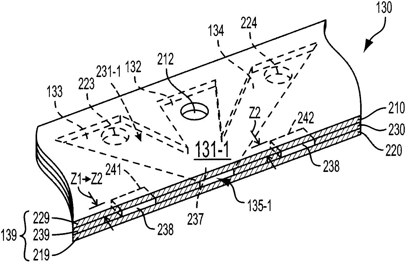
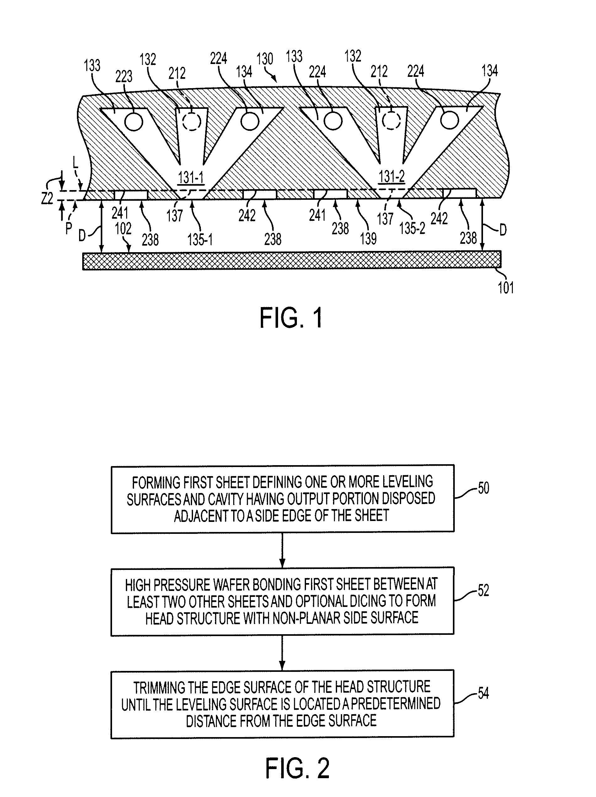
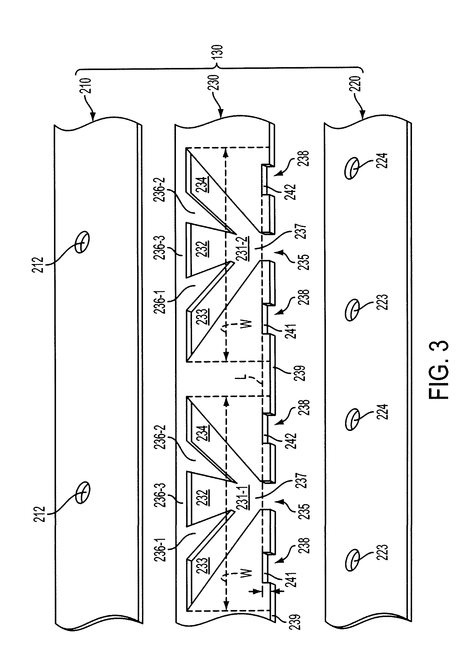
[0023]FIG. 1 illustrates a portion of an extrusion head 130, which makes up part of a micro extrusion apparatus for producing extruded structures on a substrate 101 in accordance with an embodiment of the present invention. As set forth in additional detail below, extrusion head 130 includes multiple sheets (e.g., metal plates) that form multiple fluidic channels (e.g., fluidic channels 131-1 and 131-2) that extrude material through associated outlet orifices (e.g., outlet orifices 135-1 and 135-2) that are arranged along an edge surface 139 (shown in edge view in FIG. 1). Each fluidic channel (e.g., fluidic channel 131-1) includes a central channel 132 positioned between opposing (first and second) side channels 133 and 134, with all three channels communicating with associated outlet orifice 135-1 by way of an output junction (output portion) 137. Each central channel 132 has a substantially isolated inlet end and an opposing outlet end that coincides with output junction 137. Sim...


PUM

PropertyMeasurementUnit
widthaaaaaaaaaa
thicknessaaaaaaaaaa
aspect ratioaaaaaaaaaa

Abstract

A co-extrusion head for forming high-aspect ratio gridline structures in a micro extrusion apparatus includes multiple sheets (e.g., metal plates) that are machined and assembled to define three-part fluidic channels having associated outlet orifice disposed along an edge surface of the head. Reference surfaces are also etched in the sheets and are aligned in a straight line that intersects output junctions of the three-channel cavities. After assembly (e.g., using high pressure bonding techniques), each reference surface is located inside a notch defined in the edge surface. The edge surface of the co-extrusion head is then trimmed (e.g., machined by wire EDM) using the reference surfaces as a precise guide, thereby producing uniform length outlet orifices with uniform flow impedance.

Description

FIELD OF THE INVENTION[0001]The present invention is related to micro extrusion systems and methods, and more particularly to methods for fabricating extrusion heads for simultaneously producing a large number of relatively fine extruded structures.BACKGROUND[0002]With traditional extrusion a billet of material is pushed and / or drawn through a die to create a rod, rail, pipe, etc. Various applications leverage this capability. For instance, extrusion can be used with food processing applications to create pasta, cereal, snacks, etc., pipe pastry filling (e.g., meringue), pattern cookie dough on a cookie pan, generate pastry flowers and borders on cakes, etc. In another application, extrusion can be used with consumer goods, for example, to merge different colored toothpastes together on a toothbrush.[0003]Micro extrusion involves the extrusion of fine featured (e.g., less than 50 micron width and height) structures on a target substrate. Extrusion heads for micro extrusion systems t...

Claims


Application Information

Patent Timeline
Patent Type & Authority Patents(United States)
IPC IPC(8): B32B38/10B81C99/00B29C48/05B29C48/30B29C48/345
CPCB29C47/0014B29C47/0021B81C99/0015Y10T156/108B29C47/30B29C48/05B29C48/08B29C48/345
Inventor FORK, DAVID K.ZIMMERMAN, THOMAS S.
Owner SOLARWORLD INNOVATIONS
Why Eureka
Try Eureka