Illuminated infusion cannula

a cannula and light source technology, applied in the field of surgical instruments, can solve the problems of low light transmittance, undesirable fluid flow rate, and inability to separate the infusion portion and the eye, and achieve the effect of high light transmittance, high fluid flow rate, and high flow ra

Active Publication Date: 2010-08-24
ALCON INC
View PDF10 Cites 82 Cited by
  • Summary
  • Abstract
  • Description
  • Claims
  • Application Information

AI Technical Summary

Benefits of technology

[0010]Embodiments of the present invention provide a system and method for illuminating an area during eye surgery that substantially addresses the above identified needs as well as other needs. One embodiment provides a transparent illuminated infusion cannula operable to illuminate an area during eye surgery. An optical fiber may be spaced a certain distance away from the cannula such that fluid flow around the distal end of the fiber and into the transparent cannula may occur with a much higher flow rate than what had previously been possible. The fiber cannula airspace may be optimized so that the cross-sectional area of the fluid conduit remains substantially constant in order to achieve a best compromise between high light transmittance and high fluid flow rate.

Problems solved by technology

Moreover, the fibers are run directly within the infusion channel, and illumination and infusion portions are non-separable near the eye.
These disadvantages include undesirably low light transmittance and undesirable fluid flow rates, particularly when combined in, for example, a 20 gauge cannula.

Method used


Image

  • Illuminated infusion cannula
  • Illuminated infusion cannula
  • Illuminated infusion cannula

Examples


Embodiment Construction

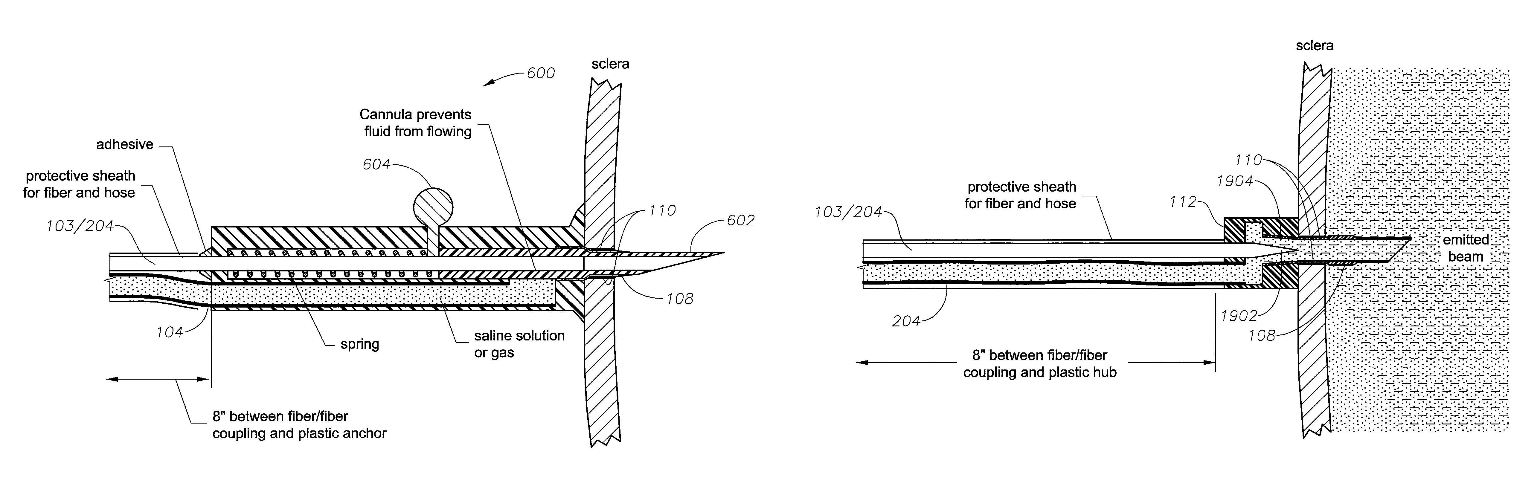
[0029]Preferred embodiments of the present invention are illustrated in the FIGs., like numerals being used to refer to like and corresponding parts of the various drawings.

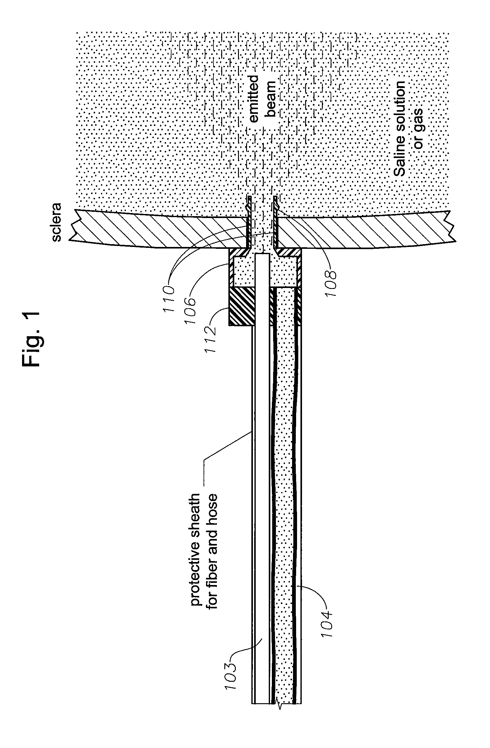
[0030]FIG. 1 provides a representation of a transparent illuminated infusion cannula's downstream end in accordance with embodiments of the present invention. This embodiment provides an illuminated infusion cannula 100 that may include the following components: (1) an endo-illuminator 100 incorporating a tapered high numerical aperture (NA) optical fiber 101, such as a belled 20 mil diameter 0.63 NA Toray fiber 103, (2) a hose 104 for the transport of liquid or gas, (3) a hub 106 where the endo-illuminator and hose come together, (4) a transparent cannula 108 downstream from the hub which may incorporate a self-retaining ring, and (5) and a highly reflective coating 110 on a portion of the outer side surface of the cannula. Optionally the distal portion of the transparent cannula may be curved or may incorporate...


PUM


Abstract

A transparent illuminated infusion cannula is provided for illuminating an area during eye surgery. An optical fiber may be spaced a certain distance away from the cannula such that fluid flow around the distal end of the fiber and into the transparent cannula may occur with a much higher flow rate than what had previously been possible. The fiber cannula airspace may be optimized so that the cross-sectional area of the fluid conduit remains substantially constant in order to achieve a best compromise between high light transmittance and high fluid flow rate.

Description

RELATED APPLICATIONS[0001]This application claims the benefit of, priority to, and incorporates by reference in its entirety for all purposes U.S. Provisional Application No. 60 / 751,175 entitled “Transparent Illuminated Infusion Cannula” filed on Dec. 16, 2005.[0002]This application is related to and incorporates by reference in its entirety for all purposes U.S. Provisional Application No. 60 / 653,265 filed on Feb. 15, 2005, entitled “High Throughput Endo-Illuminator Probe.”[0003]This application is related to and incorporates by reference in its entirety for all purposes U.S. Non-Provisional application Ser. No. 11 / 354,615 filed on Feb. 15, 2006, entitled “High Throughput Endo-Illuminator Probe.”TECHNICAL FIELD OF THE INVENTION[0004]The present invention relates generally to surgical instrumentation. In particular, the present invention relates to surgical instruments for illuminating an area during eye surgery. Even more particularly, the present invention relates to an infusion i...

Claims


Application Information

Patent Timeline
Patent Type & Authority Patents(United States)
IPC IPC(8): A61N1/30A61B18/18
CPCA61B17/3421A61F9/00736A61B2017/3419A61B2019/5206A61M2210/0612A61M5/158A61M2205/587A61B2090/306A61F9/007
Inventor SMITH, RONALD T.AULD, JACK R.MCCOLLAM, CHRISTOPHERLIN, DEAN Y.HICKINGBOTHAM, DYSON
Owner ALCON INC
Why Eureka
Try Eureka