Instruction fetch control device and method thereof with dynamic configuration of instruction buffers

a control device and instruction buffer technology, applied in the field of instruction buffer control devices and dynamic configuration of instruction buffers, can solve the problems of large trace cache capacity, large entry size (capacity), and difficulty in ensuring trace cache capacity sufficient to cover a wide instruction area, so as to improve the efficiency of instruction buffer use

Inactive Publication Date: 2010-08-24
FUJITSU LTD
View PDF14 Cites 60 Cited by
  • Summary
  • Abstract
  • Description
  • Claims
  • Application Information

AI Technical Summary

Benefits of technology

[0017]The present invention has been made to solve the disadvantages and problems described above. It is an object of the present invention to improve the use efficiency of instruction buffers and to make the instruction buffers as compact as possible.
[0019]According to such a configuration, an instruction buffer storing an instruction string to be supplied next to an instruction string stored in the instruction buffer is designated by the designation unit. In this way, instruction buffers can be dynamically configured and the use efficiency of instruction buffers can be improved in a compact configuration.
[0021]According to such a configuration, an instruction buffer storing a subsequent instruction string to be supplied next to the instruction string stored in the instruction buffer is designated by the designation unit. In this way, instruction buffers can be dynamically configured and the use efficiency of instruction buffers can be improved in a compact configuration.
[0023]According to such a configuration, an instruction buffer storing a branch prediction target instruction string to be supplied next to the instruction string stored in the instruction buffer is designated by the designation unit. In this way, instruction buffers can be dynamically configured and the use efficiency of instruction buffers can be improved in a compact configuration.

Problems solved by technology

However, since in this configuration, decoded information is stored, entry size (capacity) becomes large, which is a disadvantage.
Therefore, large trace cache capacity is needed in a specific instruction area.
In this case, it is difficult to secure trace cache capacity sufficient to cover a wide instruction area.
Therefore, in the case of mis-trace caching, an overhead becomes large.
However, even an instruction cache is miss-traced in an actual environment where a plurality of applications are executed, as in a server performing a large-scale transaction process.
Therefore, in a trace cache that covers a narrower instruction area than that of an instruction cache, there are frequent mis-traces.
In other words, a configuration using a trace cache is not effective in an actual environment, even worse, process performance remarkably degrades.
Therefore, such control becomes complex.
For example, when it is necessary to rewrite an instruction string due to store instruction, processes for updating and nullifying a trace cache become complex and the control unit requires a complex design accordingly, which is another disadvantage.
However, in the configuration using this instruction buffer, the average efficiency in use of an instruction buffer is low since the instruction buffer is static, which is another problem.
Therefore, the use efficiency also becomes low.
In the case of a static instruction buffer configuration in which instruction buffers are fixedly determined depending on whether a branch as been predicted, the use efficiency of instruction buffers varies depending on the number of branch predictions and the use efficiency of the used instruction buffers becomes low, which is a problem.
Long distance wiring naturally caused by recent giant configurations due to the recent miniaturization of LSI processes has been the major factor obstructing high-speed operation, and the increase in the number of trace caches and instruction buffers incurs a great disadvantage.

Method used


Image

  • Instruction fetch control device and method thereof with dynamic configuration of instruction buffers
  • Instruction fetch control device and method thereof with dynamic configuration of instruction buffers
  • Instruction fetch control device and method thereof with dynamic configuration of instruction buffers

Examples


Embodiment Construction

[0040]The preferred embodiments of the present invention are described below with reference to the drawings.

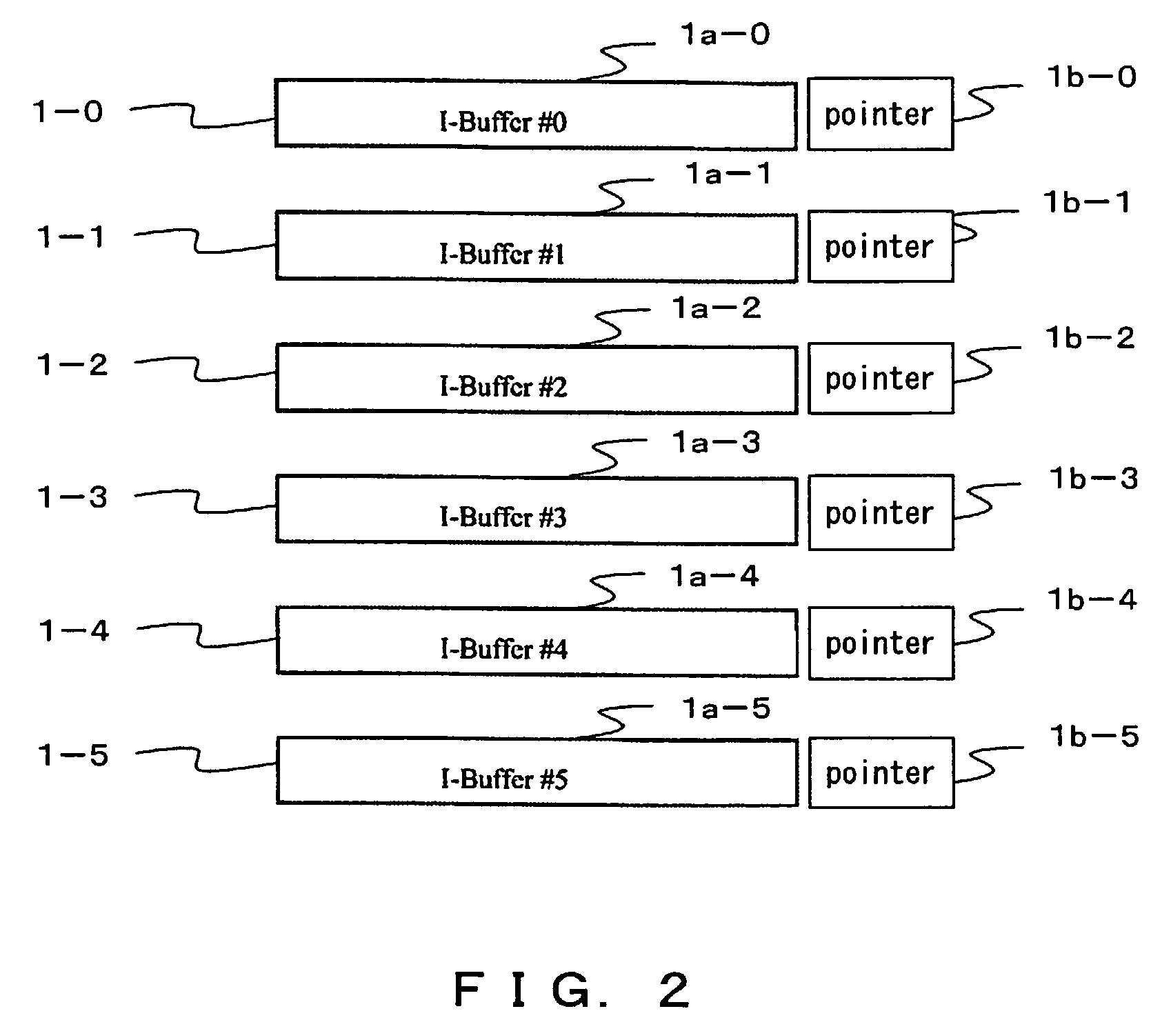
[0041]FIG. 2 shows an example of the conceptual configuration of an instruction buffer used in an instruction fetch control device according to the one preferred embodiment of the present invention.

[0042]As shown in FIG. 2, the configuration comprises six instruction buffers 1-i (i=0, 1, 2, 3, 4, 5) (I-Buffer#0, #1, #2, #3, #4 and #5 in FIG. 2). In this example, although the number of instruction buffers is six, it is not limited to six.

[0043]Each instruction buffer 1-I (i=0 through 5) further comprises data sections 1a-i (i=0, 1, 2, 3, 4, 5) storing instruction strings and pointer sections 1b-i (i=0, 1, 2, 3, 4, 5) designating an instruction buffer 1 storing an instruction string to be supplied next to an instruction buffer stored in the relevant instruction buffer 1 (pointer in FIG. 2). The relevant instruction buffer 1 and an instruction buffer 1 storing an instruction stri...


PUM


Abstract

This is an instruction fetch control device supplying instructions to an instruction execution unit. The device comprises a plurality of instruction buffers storing an instruction string to be supplied to the instruction execution unit and a designation unit designating an instruction buffer storing the instruction string to be supplied next for each of the plurality of instruction buffers.

Description

BACKGROUND OF THE INVENTION[0001]1. Field of the Invention[0002]The present invention relates to a data processing device and in particular, relates to an instruction fetch control device for fetching an instruction and feeding it to an instruction execution unit (instruction execution processing unit) and a method thereof.[0003]2. Description of the Related Art[0004]In a data processing device adopting an advanced instruction processing method such as a pipeline processing system or subsequent ones, performance has been improved by speculatively fetching a subsequent instruction (fetch instruction) and speculatively processing the instruction without waiting until the execution of the current instruction has completed.[0005]In such a data processing device, for example, by providing an instruction fetch unit that is completely decoupled from an instruction execution unit closely coupled with a branch prediction mechanism, sufficient instruction fetching capacity needed by the instr...

Claims


Application Information

Patent Timeline
Patent Type & Authority Patents(United States)
IPC IPC(8): G06F9/00G06F15/00G06F9/38
CPCG06F9/3804
Inventor UKAI, MASAKI
Owner FUJITSU LTD
Why Eureka
Try Eureka