Method and apparatus for conveying material and ejector apparatus

a technology of ejector apparatus and conveying method, which is applied in the direction of conveyors, non-positive displacement pumps, and liquid separation agents, etc. it can solve the problems of affecting so as to improve the efficiency of ejector apparatus, improve the effect of negative pressure and increase the negative pressur

Active Publication Date: 2010-08-31
MARICAP OY
View PDF14 Cites 15 Cited by
  • Summary
  • Abstract
  • Description
  • Claims
  • Application Information

AI Technical Summary

Benefits of technology

[0010]The solution of the invention has numerous significant advantages. By limiting the admission of gases into the ejector tube or to its vicinity from the “wrong end”, it is possible to improve the efficiency of the ejector apparatus according to need and to increase the negative pressure, e.g. in a blockage situation occurring in the material conveying conduits. By bringing the outlet end of the ejector tube below the level of the liquid surface, a very effective solution for improving the negative pressure produced by the ejector is achieved while the entry of leakage flow into the ejector tube in a direction opposite to the spraying direction of the ejector nozzle is prevented. By using a liquid mist as operating medium, a very strong suction effect and a very good yield are achieved. In addition, a considerable energy saving effect, even 50% as compared to a pneumatically operated ejector apparatus is achieved. In addition, liquid mist is a very efficient medium for removing particles and reducing the disadvantages of smell with the ejector device. By arranging around the ejector tubes a shell part provided with an opening, preferably an opening provided with a closing element, for the outlet of conveying air. By arranging for the closing element of the openings to close e.g. in a blockage situation occurring in the conveying conduit, the suction effect of the ejector can be improved. At the same time, clearance of the blockage is promoted. By arranging a circulation of the operating medium to be sprayed, a very strong effect reducing the water consumption is achieved. In addition, if desirable and necessary, it is possible to add chemicals to the operating medium. By arranging a coaxial nozzle in the suction pipe, the efficiency of the ejector can be further improved. By producing a rotating motion in the liquid separated in the separating element, possible impurities can be more effectively separated from the liquid and prevented from getting into the liquid suction pipes. By additionally providing the apparatus with an option for feeding a second medium into the ejector device, it is possible, on the one hand, to further advantageously reduce possible smell problems at the ejector device while at the same time improving the efficiency of suction. By supplying a second medium together with the operating medium and, if necessary, using the pressure of the operating medium for conveying and / or feeding the second medium into the ejector space, a very advantageous and effective solution is achieved. By arranging the nozzle for the second medium in the same assembly with the nozzle for the operating medium, a sensible solution in respect of manufacturing technology is achieved. At the same time, a good solution for improving the suction of the ejector device is achieved. When a substance of a higher density, such as a liquid, preferably water, is used, the suction effect can be improved. On the other hand, by supplying a second medium, the suction effect can be further improved even if the operating medium is a liquid or a mixture of liquid and gas. When a liquid is used as the operating medium and / or at least as the second medium, the gas flow can be washed by spraying this liquid, thereby eliminating possible disadvantages regarding particles and smell. Using a separate pump to supply the second medium allows easy control of its supply. In addition, the ratio between operating medium and second medium can be adjusted at the same time. By adjusting the pressure of the operating medium going to the ejector as necessary, significant energy savings are achieved. In addition, by adjusting the pressure, it is possible to influence the suction produced by the ejector, which is a handy way of adjusting the negative pressure and / or pressure difference in the material conveying conduit as well. By implementing the pressure adjustment using parallel flow paths provided with a throttle element and a valve which is opened and closed on the basis of impulses received from the control system, a very usable and easily modifiable adjustment system is achieved. If desirable, the conveying of material can be started with a higher pressure produced in the ejector and the pressure can be reduced as the conveying process advances. Different supply stations of the system can handle different materials, for which it is possible to set different pressure requirements and thus the settings affecting the conveying of the materials. On the other hand, in conjunction with different supply stations it is possible to arrange a switch that the operator can use to define, e.g. according to the material being supplied, the pressure values to be used in conveying the material. By arranging for the throttle elements to be adjustable, the versatility of the system can be further improved, so it can be adapted for the conveying of materials of different kinds. The system provides a possibility of e.g. varying the pressure difference / (negative) pressure in the material conveying conduit, and this property can be further extended by arranging according to the invention an openable and closeable connection for pneumatic air to the material conveying conduit. By using, according to an embodiment of the invention, means for observing the flow in the suction pipe between the separating device and the ejector device, the operation of the apparatus can be regulated on the basis of variations in this flow. By further arranging for the material removal means of the separating device to function on the basis of commands given by the regulating system, and additionally preferably to use pneumatic air as their operating medium, the functionality of the system can be further improved. The solution of the invention is excellently applicable for use for conveying other types of material as well, such as waste produced in engineering industry, e.g. for conveying chips. The ejector device of the invention can be used in conjunction with many types of conveying systems. Moreover, the ejector device can be used as a vacuum generator in conjunction with applications requiring a negative pressure, such as e.g. wood drying apparatus, suction graspers, smoke removal systems, dust removal systems. The ejector device is very well applicable for use in conjunction with explosible substances.

Problems solved by technology

In possible blockage situations in the conveying conduit system, prior-art solutions have a limited applicability for clearing blockages or they require separate apparatus for this purpose.
Further, current solutions have limitations regarding adaptation to conveying materials involving different requirements.
Moreover, in prior-art solutions the material to be conveyed may cause problems of smell and / or particles in the blast air of the vacuum apparatus, such as an ejector apparatus.
The use of conventional vacuum pumps in conjunction with or in the environment of explosible materials is very restricted or even dangerous.

Method used


Image

  • Method and apparatus for conveying material and ejector apparatus
  • Method and apparatus for conveying material and ejector apparatus
  • Method and apparatus for conveying material and ejector apparatus

Examples


Embodiment Construction

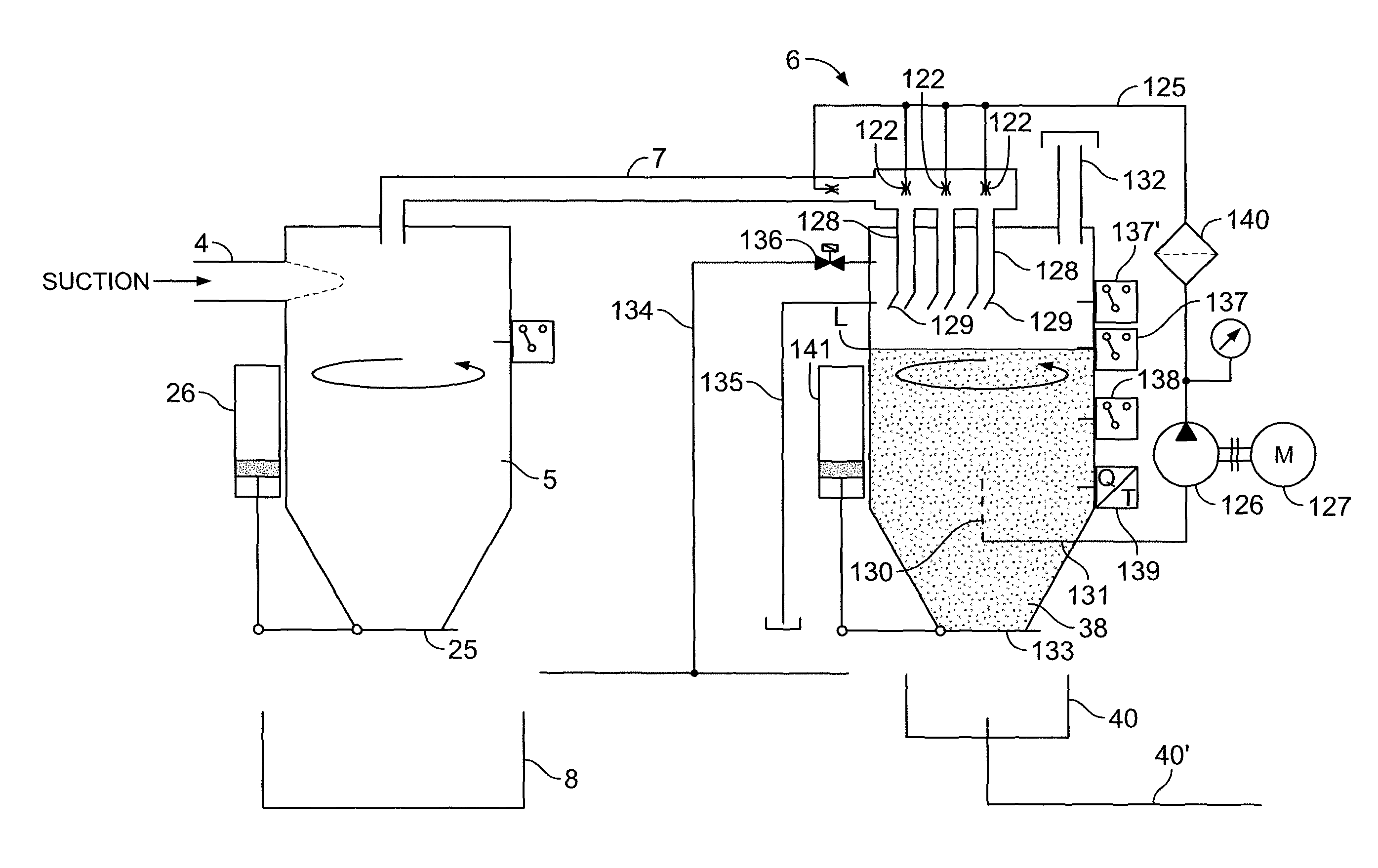
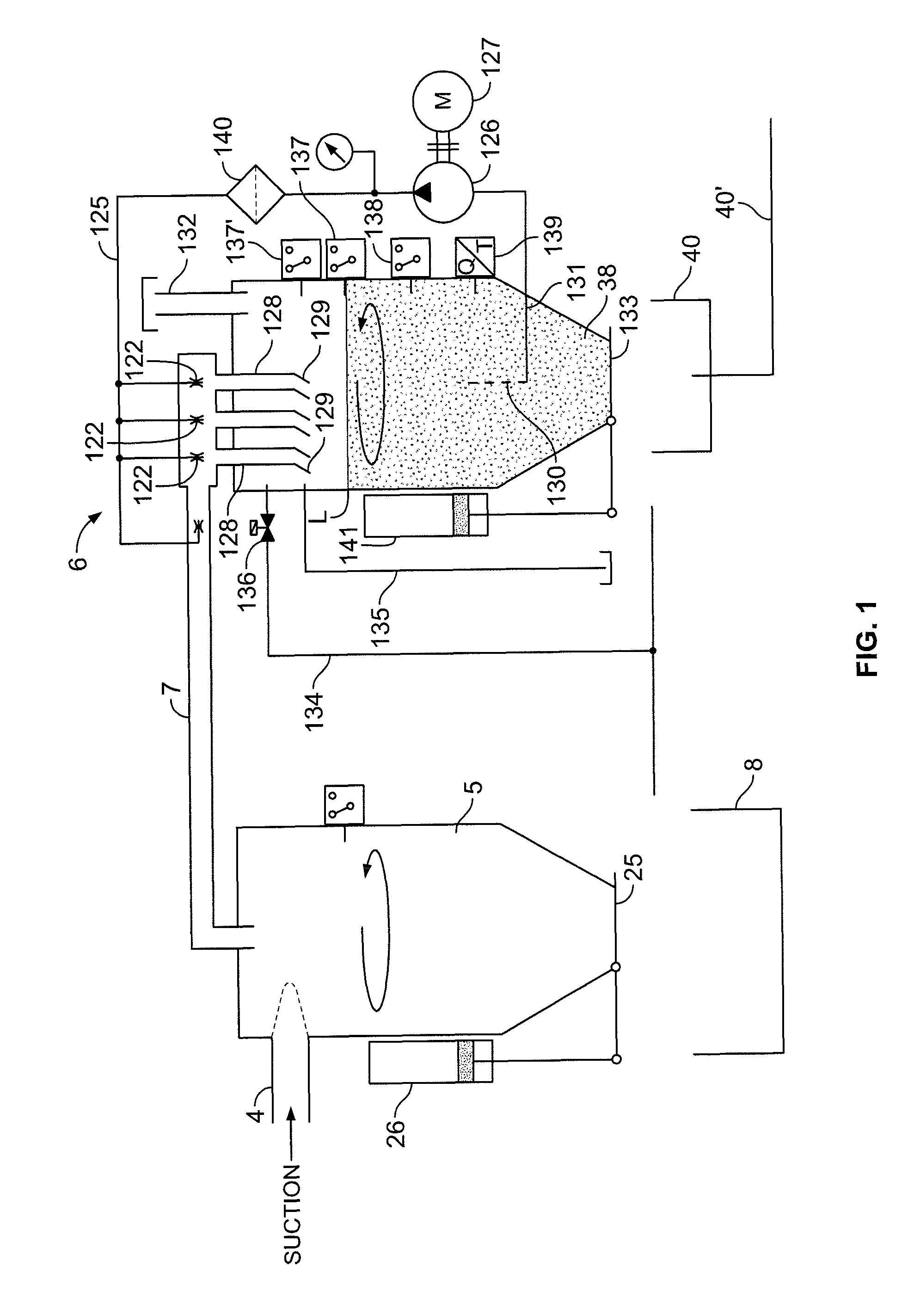
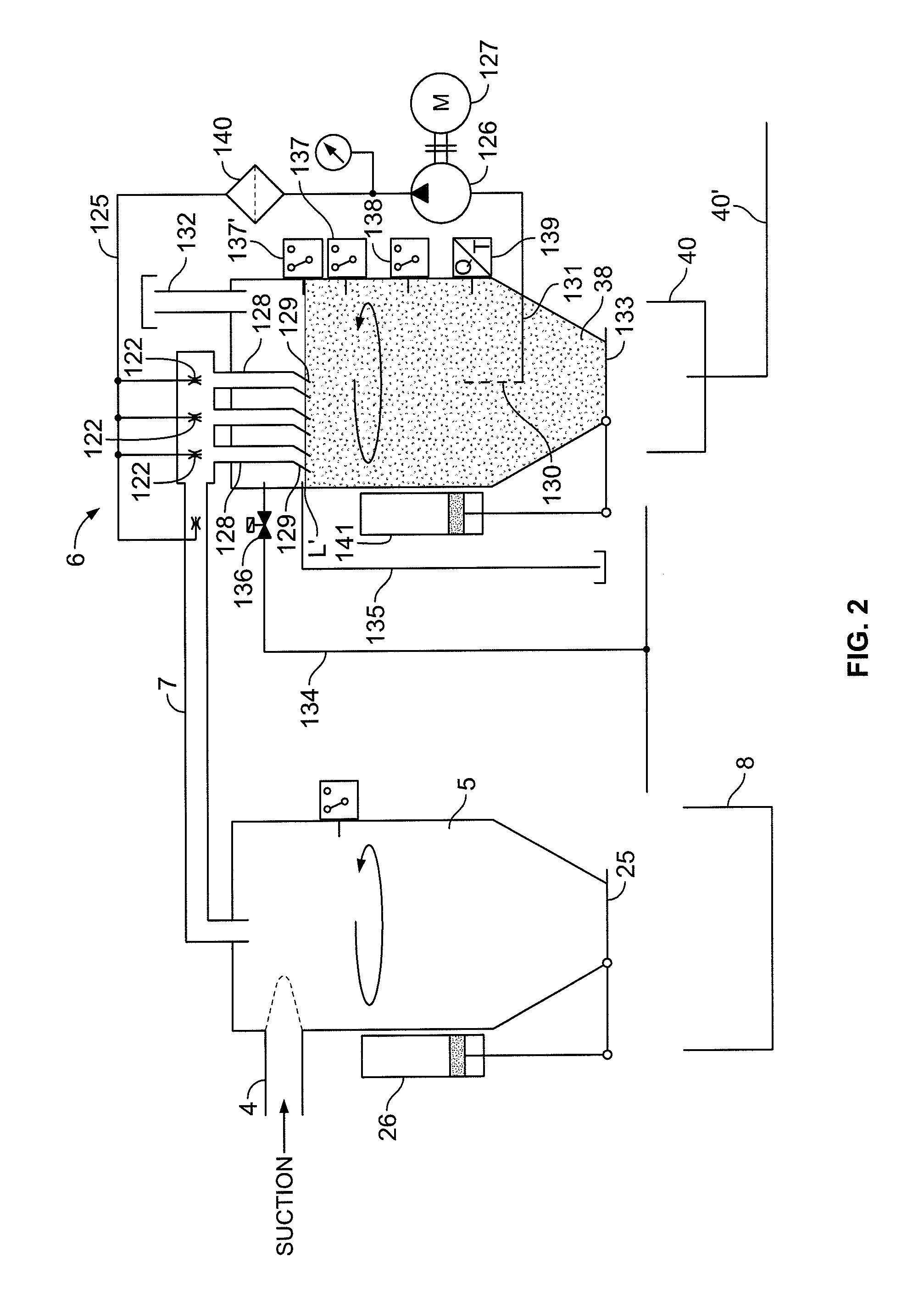
[0019]The conveying conduit system typically comprises a main conveying conduit 4, to which a plurality of supply stations may be connected via feed pipes. The figure shows only part of the main conveying conduit 4. The material supplied is conveyed along the conveying conduit system into a separating device 5 placed at the termination of the conveying conduit system. In the separating device, the material conveyed is separated e.g. by centrifugal force from the conveying air. The separated material is removed, e.g. according to need, from the separating device 5 into a material container 8 or into a further processing stage. In the embodiment illustrated in the figures, the separating device 5 is provided with material removal elements 25, 26. From the separating device 5, a conduit 7 leads into a vacuum unit 6. The vacuum unit produces in the conveying conduit system 4 the negative pressure required for conveying the material. In the solutions illustrated in the figures, the vacuu...


PUM

PropertyMeasurementUnit
angleaaaaaaaaaa
droplet sizeaaaaaaaaaa

Abstract

A method for conveying material by applying a pressure difference in a conveying conduit (4), in which method the material is fed into the conveying conduit (4) and in the conveying conduit further into a separating device (5), where the material being conveyed is separated from conveying air, in which method a negative pressure is created in the conveying conduit (4) by means of an ejector apparatus (6), whose suction side is connected to the separating device (5), said ejector apparatus being operated using an operating medium consisting of a liquid mist, especially an aqueous liquid mist, said medium being sprayed through at least one spraying nozzle (122) into an ejector tube (128) directed into a separating element (38). In the method, the generation of the negative pressure to be produced is intensified according to need by limiting the flow of gases, such as air, into the ejector tube (128) from the direction opposite to the spraying direction of its operating medium, i.e. from the outlet end (129) of the ejector tube. The invention also relates to an apparatus and an ejector device.

Description

BACKGROUND OF THE INVENTION[0001]The present invention relates to a method for conveying material by applying a pressure difference in a conveying conduit, in which method the material is fed into the conveying conduit and in the conveying conduit further into a separating device, where the material being conveyed is separated from the conveying air, in which method a negative pressure is created in the conveying conduit by means of an ejector apparatus, whose suction side is connected to the separating device, said ejector apparatus being operated using an operating medium, which consists of a liquid mist, especially an aqueous liquid mist, said medium being sprayed through at least one spraying nozzle into an ejector tube directed into a separating element.[0002]The invention also relates to an apparatus for conveying material, preferably bulk material in food industry, in particular slaughtering offal and food waste, or working residual in engineering industry, by the application...

Claims


Application Information

Patent Timeline
Patent Type & Authority Patents(United States)
IPC IPC(8): B65G53/00
CPCB01D47/06B65G53/24F04F5/52F04F5/04B65G53/62B01D47/10
Inventor SUNDHOLM, GORAN
Owner MARICAP OY
Why Eureka
Try Eureka