
Prosthetic knee and leg assembly for use in athletic activities in which the quadriceps are normally used for support and dynamic function

a technology of pros which is applied in the field of prosthetic knees and lower legs, can solve the problems of not being able to function well and not being designed for products, and achieve the effect of shortening the distance and less for

Inactive Publication Date: 2010-08-31
FRYE JR TODD JAREM
View PDF3 Cites 13 Cited by
  • Summary
  • Abstract
  • Description
  • Claims
  • Application Information

AI Technical Summary

Benefits of technology

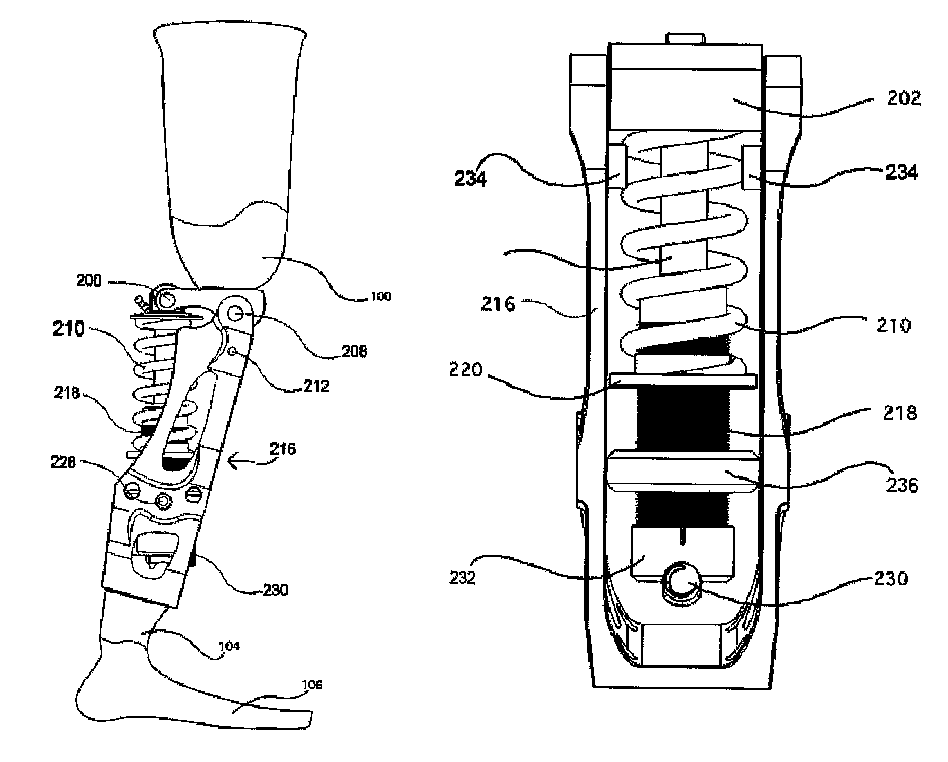
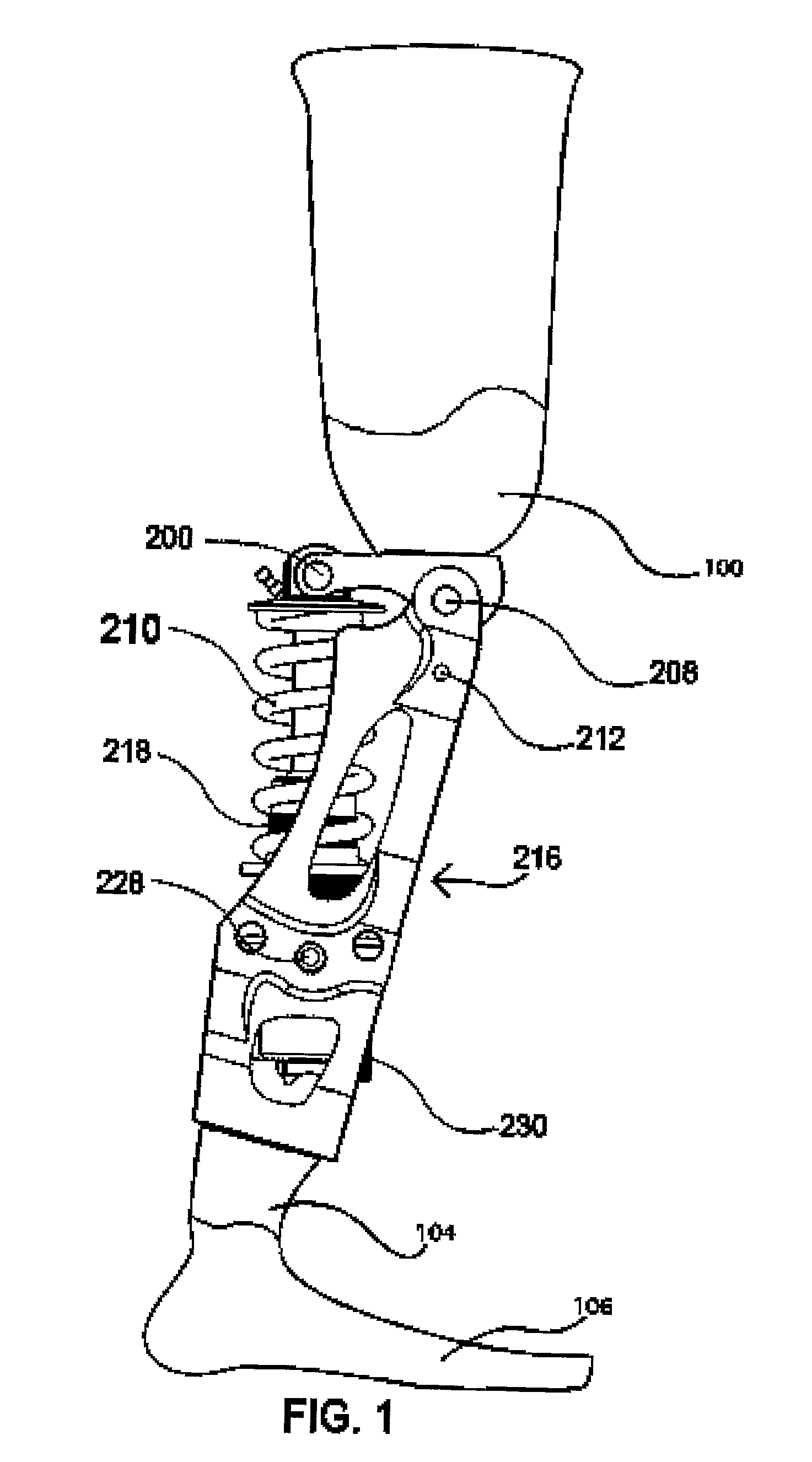
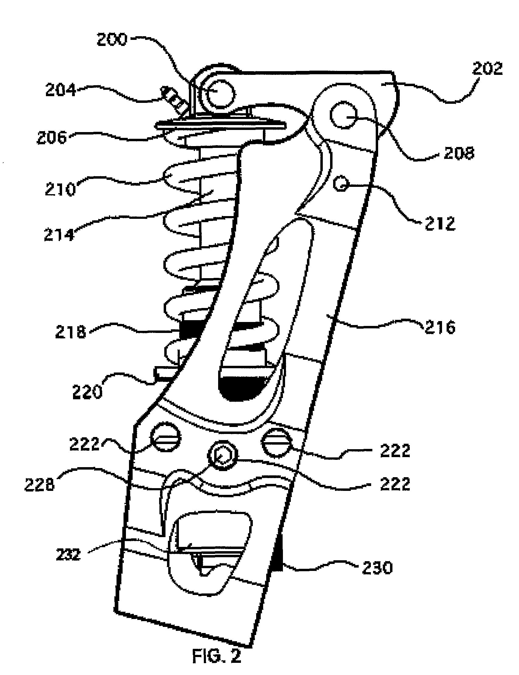
[0012]The new prosthetic knee and lower leg device includes residual thigh attachment plate that is pivotally coupled to a shin frame with a first titanium axle passing through both the residual thigh attachment plate and the shin frame that rides in sealed needle bearing assemblies. The shin frame, which functions as a lower leg piece, is machined from a solid aluminum billet. A suspension strut, which functions as the amputee's missing quadriceps, is coupled to the residual thigh attachment plate with a second titanium axle and to the shin frame with an adjustable-height trunnion. The first and second titanium axles are axially spaced from one another. The suspension strut has a generally cylindrical main body with a threaded lower portion. An internally-threaded lower spring retention collar engages the threaded lower portion and can be axially rotated to raise or lower it height with respect to the main body, thereby adjusting the amount of tension on a coil spring, which fits over the cylindrical main body. A trunnion mount is also threaded and engages the threaded lower portion. By adjusting the position of the trunnion mount with respect to the cylindrical main body, the distance between the trunnion and the second titanium axle can be varied. By adjusting this distance, the angle that the residual thigh attachment plate makes with the shin frame can be changed. The shorter the distance, the more bent the knee. The can be installed in one of three locations in the shin frame. The middle location corresponds to a normal location. When fixed to the rear location, the control unit functions much like a compound bow, becoming less forceful at full compression, but still ready to spring back into action. This position makes it easier for a telemark skier to stay in a turn position on steeper terrain in which his gravitational pull is not placed directly above the knee as it is on flat ground. In the front position, compression over the full range is much more linear giving constant tension and full rebound throughout the range of motion. This works well for activities such as snow boarding and surfing in which the user must have a stable knee at all times but be able to absorb shock and move dynamically.

Problems solved by technology

The product is not designed, nor does it function well, as a walking or running leg.

Method used


Image

  • Prosthetic knee and leg assembly for use in athletic activities in which the quadriceps are normally used for support and dynamic function
  • Prosthetic knee and leg assembly for use in athletic activities in which the quadriceps are normally used for support and dynamic function
  • Prosthetic knee and leg assembly for use in athletic activities in which the quadriceps are normally used for support and dynamic function

Examples


Embodiment Construction

[0020]The invention will now be described with reference to the included drawing FIGS. 1 through 7.

[0021]Referring now to FIGS. 2, 3, 4 and 5, the new prosthetic knee and lower leg device includes a shin frame 216 that is pivotally coupled to a residual thigh attachment plate 202 with an artificial knee joint formed by a first titanium axle 208 which passes through the residual thigh plate 202 and extends into opposite sides of the shin frame 216. The residual thigh plate 202 has recesses on each side thereof, each of which houses a sealed needle bearing assembly 246. The first titanium axle 208 is secured on one end by a first set screw 238. The needle bearing assemblies 246 enable the residual thigh plate 202 to rotate about the first titanium axle 208. The inner race of each needle bearing assembly 246 remains stationary with respect to the first titanium axle 208, and the outer race of each needle bearing assembly 246 remains stationary with respect to the residual thigh attachm...


PUM


Abstract

The present invention provides a new prosthetic knee and lower leg device that enables an above-the-knee amputee to participate in demanding athletic activities in which the quadricep muscles are used extensively for support and dynamic function. The prosthetic device includes a residual thigh attachment plate that is pivotally coupled to a shin frame. An adjustable suspension strut is coupled to both the residual thigh attachment plate and the shin frame. The functional length of the strut can be adjusted, as can be the lower mounting position thereof. The prosthetic device can be adjusted with regard to functional characteristics, performance settings, and “home position” angles of the knee. The extent of adjustability enables the user to adapt the device for different levels of aggressiveness, different activities and different circumstances, and also allows the device to be adapted to users of different weights and size.

Description

BACKGROUND OF THE INVENTION[0001]1. Field of the Invention[0002]This invention relates generally to prosthetic devices and, more particularly, to a prosthetic knee and lower leg assembly which enables an individual, who has had a leg amputation between the hip and knee joints, to participate in demanding athletic activities, such as telemark skiing, alpine skiing, cross-country skiing, water skiing, snow boarding, wake boarding, surfing, skate boarding, wind surfing, rock climbing, ice climbing, roller blading and ice skating, in which the quadriceps are ordinarily used extensively for support and dynamic function.[0003]2. History of the Prior Art[0004]A prosthetic device incorporating a joint for articulation of the knee is an essential element of an artificial leg prosthesis called an “above the knee”, that is to say which has a foot, an ankle, a lower leg portion (hereinafter called a “leg”), a knee and a socket for receiving the stump of the thigh.[0005]Relative movement of the ...

Claims


Application Information

Patent Timeline
Patent Type & Authority Patents(United States)
IPC IPC(8): A61F2/64A61F2/68
CPCA61F2/60A61F2/64A61F2002/5006A61F2002/503A61F2002/5073A61F2002/607A61F2002/747A61F2/74
Inventor FRYE, JR., TODD JAREM
Owner FRYE JR TODD JAREM
Learn More