Plasma generator, plasma control method, and method of producing substrate

a plasma generator and control method technology, applied in the field of plasma generators, can solve the problems of insufficient plasma treatment, difficult system, 1 to obtain adequate strength, etc., and achieve the effects of reducing the load on the rf power source, high densities, and high densities

Active Publication Date: 2010-08-31
JAPAN SCI & TECH CORP +3
View PDF66 Cites 9 Cited by
  • Summary
  • Abstract
  • Description
  • Claims
  • Application Information

AI Technical Summary

Benefits of technology

[0023]When an RF power is supplied from the power source to the antennas, each antenna radiates the induction electromagnetic field, thereby generating plasma. According to the present invention, the antennas are arranged roughly parallel to the stage, so that the antennas are at approximately the same height from the stage. This arrangement enables the antennas to intensively supply energy into the space, thereby generating plasma with high density.
[0050]The plasma generator having the constructions described thus far is capable of producing a plasma state having high densities with a higher level of uniformity than conventional plasma generators. Use of this plasma generator enables an efficient production of a substrate having a surface with a higher degree of flatness through the deposition process or etching process.

Problems solved by technology

The most serious problem for a large-scale system is the unevenness in the plasma treatment.
However, this makes it difficult for the system of Patent Document 1 to obtain an adequate strength of electromagnetic field within the plasma-generating chamber, because the antenna is located outside the plasma-generating chamber and the thick wall attenuates the induction electromagnetic field radiated from the antenna.
In summary, the method disclosed in Patent Document 1 is effective in enhancing the uniformity of the plasma density to a certain extent but cannot adequately increase the plasma density.
Also, it is possible that the electromagnetic field radiated from the antenna forms a standing wave, which deteriorates the uniformity of the plasma.
However, the distance cannot be ignored for large substrates.

Method used


Image

  • Plasma generator, plasma control method, and method of producing substrate
  • Plasma generator, plasma control method, and method of producing substrate
  • Plasma generator, plasma control method, and method of producing substrate

Examples


first embodiment

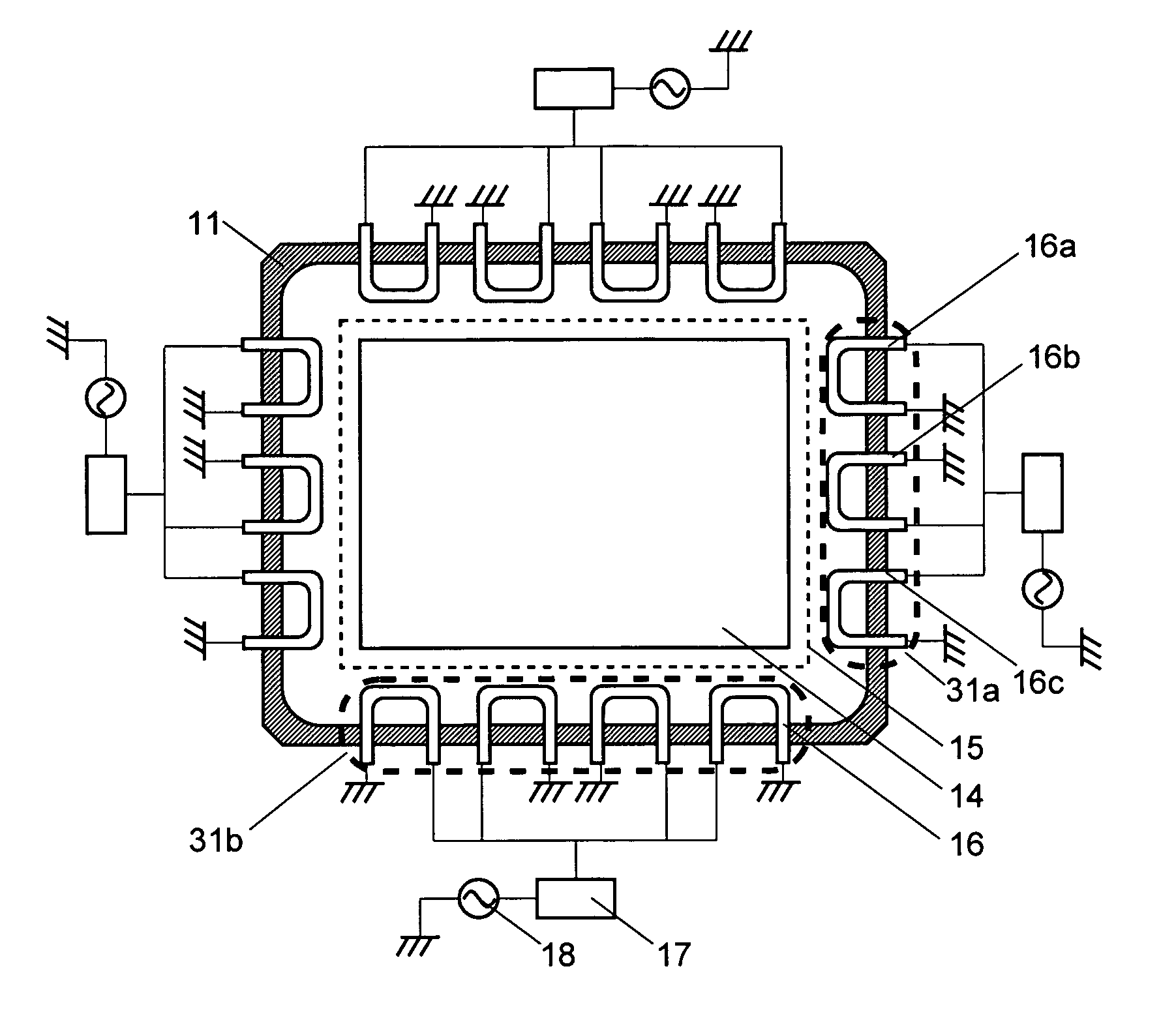
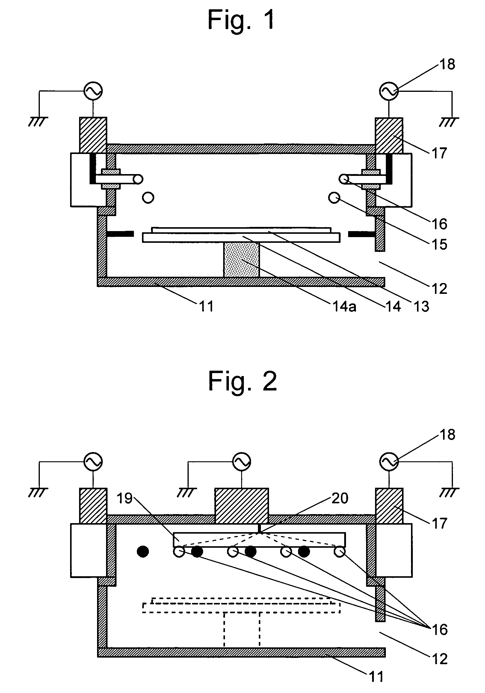
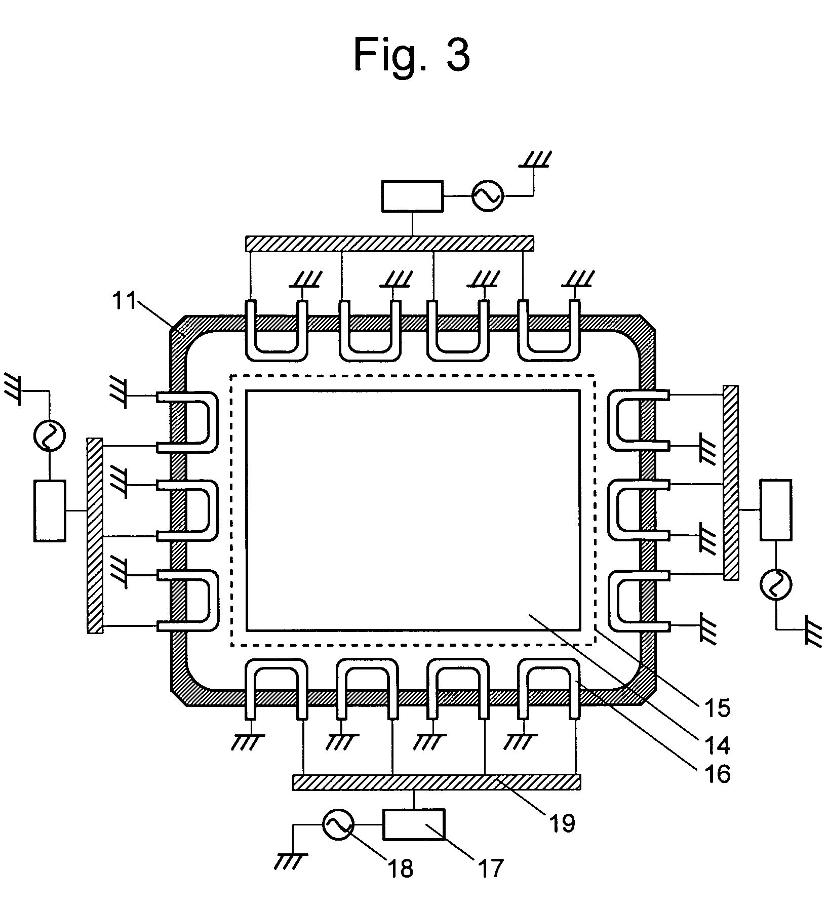
[0075]FIG. 1 is a vertical sectional view of a plasma generator as the first embodiment of the present invention, FIG. 2 is a side view of the plasma generator, and FIG. 3 is a plan view of the plasma generator.

[0076]In this plasma generator, the inner space of the vacuum chamber 11 serves as the plasma-generating chamber. As shown in FIG. 3, the horizontal shape of the inner space of the vacuum chamber 11 is rectangular, with the long side measuring 1300 mm and the short side 1000 mm. The inner space of the vacuum chamber 11 is maintained at a predetermined degree of vacuum with a vacuum pump (not shown) connected to the vacuum chamber 11. Located within the vacuum chamber 11 is a stage 14 with the long side measuring 94 cm and the short side 76 cm, on which a base plate 13 is to be placed. The stage 14 is equipped with an elevating unit 14a for moving the stage 14 in the vertical direction. At the bottom of the vacuum chamber 11, there is a doorway 12 through which the base plate ...

second embodiment

[0090]The plasma generator of the second embodiment is featured by the aspect ratio of the antennas, as described below.

[0091]FIG. 10 is a plan view of the second embodiment. The construction of this plasma generator is identical to that of the first embodiment except for the antennas 26 having a different aspect ratio. Therefore, FIG. 10 uses the same numerals used in FIG. 3 for the components that are also present in the first embodiment. The number of the RF power sources and the number of the antennas connected to each RF power source are also the same as in the first embodiment. In the plasma generator shown in FIG. 10, the aspect ratio of every antenna 26 is set to 2 (length:width=2:1), as shown in FIG. 11A, where as the aspect ratio of the antenna 16 in the first embodiment is 1 (length:width=2:1), as shown in FIG. 11B. The area S enclosed by the conductor of the antenna 26 in the second embodiment is the same as that of the antenna 16 in the first embodiment.

[0092]The follow...

third embodiment

[0098]The plasma generator of the third embodiment is featured by the polarities of the adjacent electrodes of two adjacent antennas, as described below.

[0099]FIG. 16 is a plan view of the third embodiment. The components that are present in the first embodiment are denoted by the same numeral as used in FIG. 3. The number of RF power sources and the number of antennas connected each RF power source are the same as in the first embodiment. The construction of the present plasma generator is identical to that in the first embodiment except for the RF antennas 16 whose electrodes have different polarities. More specifically, among each antenna group including three or four pieces of RF antennas located on the same sidewall, two adjacent electrodes of two adjacent RF antennas have the same polarity. Taking the antenna group 31a as an example, both of the two adjacent electrodes of the two adjacent RF antennas 16a and 16b are connected to the impedance matcher 17 and the RF power source...


PUM

PropertyMeasurementUnit
heightaaaaaaaaaa
frequencyaaaaaaaaaa
lengthaaaaaaaaaa

Abstract

The present invention aims to provide a plasma generator capable of creating a spatially uniform distribution of high-density plasma. This object is achieved by the following construction. Multiple antennas 16 are located on the sidewall of a vacuum chamber 11, and a RF power source is connected to three or four antennas 16 in parallel via a plate-shaped conductor 19. The length of the conductor of each antenna 16 is shorter than the quarter wavelength of the induction electromagnetic wave generated within the vacuum chamber. Setting the length of the conductor of the antenna in such a manner prevents the occurrence of a standing wave and thereby maintains the uniformity of the plasma within the vacuum chamber. In addition, the plate-shaped conductor 19 improves the heat-releasing efficiency, which also contributes to the suppression of the impedance.

Description

TECHNICAL FIELD[0001]The present invention relates to a plasma generator for producing a semiconductor substrate or similar substrates by using plasma to carry out a deposition or etching process on the surface of a base plate to be processed. Particularly, the present invention relates to a technique for producing a substrate of a large area by uniformly generating a plasma over that area.BACKGROUND ART[0002]In recent years, the polysilicon TFT-LCD (Thin Film Transistor Liquid Crystal Display) is drawing people's attention because it is capable of displaying images with higher luminance than the TFT-LCD that uses amorphous silicon films. In the production of a polysilicon TFT-LCD, a glass plate is coated with a polysilicon film to create a polysilicon substrate. Then, the face of the polysilicon substrate is divided into a large number of picture elements arrayed in a two-dimensional pattern, and a thin film transistor is formed on each picture element to obtain an LCD substrate. T...

Claims


Application Information

Patent Timeline
Patent Type & Authority Patents(United States)
IPC IPC(8): H01L21/00C23C16/00C23C14/00H01J37/32
CPCH01J37/321H05H1/46H05H2001/4667H05H1/4652
Inventor MIYAKE, SHOJIEBE, AKINORISHOJI, TATSUOSETSUHARA, YUICHI
Owner JAPAN SCI & TECH CORP
Why Eureka
Try Eureka