LED driver structure

a technology of led light and driver, which is applied in the direction of machines/engines, cathode-ray/electron beam tube circuit elements, instruments, etc., can solve the problems of increasing the cost of the led light system by driving ic, small reverse breakdown voltage, and poor performance of prior art, so as to achieve low price and less elements , the effect of easy impedance matching

Inactive Publication Date: 2010-08-31
ZIPPY TECH
View PDF8 Cites 8 Cited by
  • Summary
  • Abstract
  • Description
  • Claims
  • Application Information

AI Technical Summary

Benefits of technology

[0003]One objective of the present invention is to provide an LED driving circuit, which achieves a constant-current output and a lower price with fewer elements.
[0004]The present invention discloses an LED driver structure, which obtains input power coming from a power source to generate a constant-current power to drive a plurality of LEDs, and which comprises: a plurality of diode groups connected in parallel, a first piezoelectric conversion unit and a second piezoelectric conversion unit respectively arranged at both sides of the diode groups. The first and second piezoelectric conversion units receive the input power and opposite-phase convert the input power into driving powers to drive the diode groups. Among the plurality of diode groups, at least one diode group is formed of a plurality of LEDs. Each of the first and second piezoelectric conversion units has a piezoelectric inverter, which can easily achieve an impedance matching and a constant-current power via a piezoelectric effect to make the LEDs in the diode groups to emit light. The total driving power is the sum of the output powers of the first and second piezoelectric conversion units. The present invention replaces a single large-size and high-price power converter with two lower-price power converters to reduce the costs.

Problems solved by technology

However, LED has a smaller reverse breakdown voltage than general diodes, and the negative semi-period of alternating current can easily puncture LED and may externally damage LED.
Besides, the driving IC raises the cost of the LED light system.
Therefore, the prior art is expensive but has an imperfect performance.
However, the prior art has the disadvantages of non-constant current and high prices because it adopts full-wave rectification and uses at least one transformer.
In conclusion, the conventional LED driving circuits still have the problems of non-constant current (fluctuating current) and high prices to overcome.

Method used


Image

  • LED driver structure
  • LED driver structure
  • LED driver structure

Examples


Embodiment Construction

[0010]Below, the technical contents of the present invention will be described in detail in cooperation with the drawings.

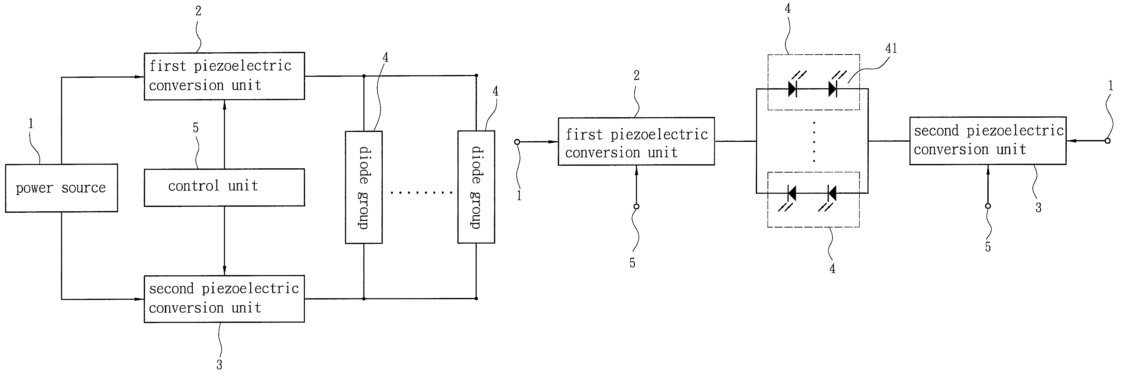
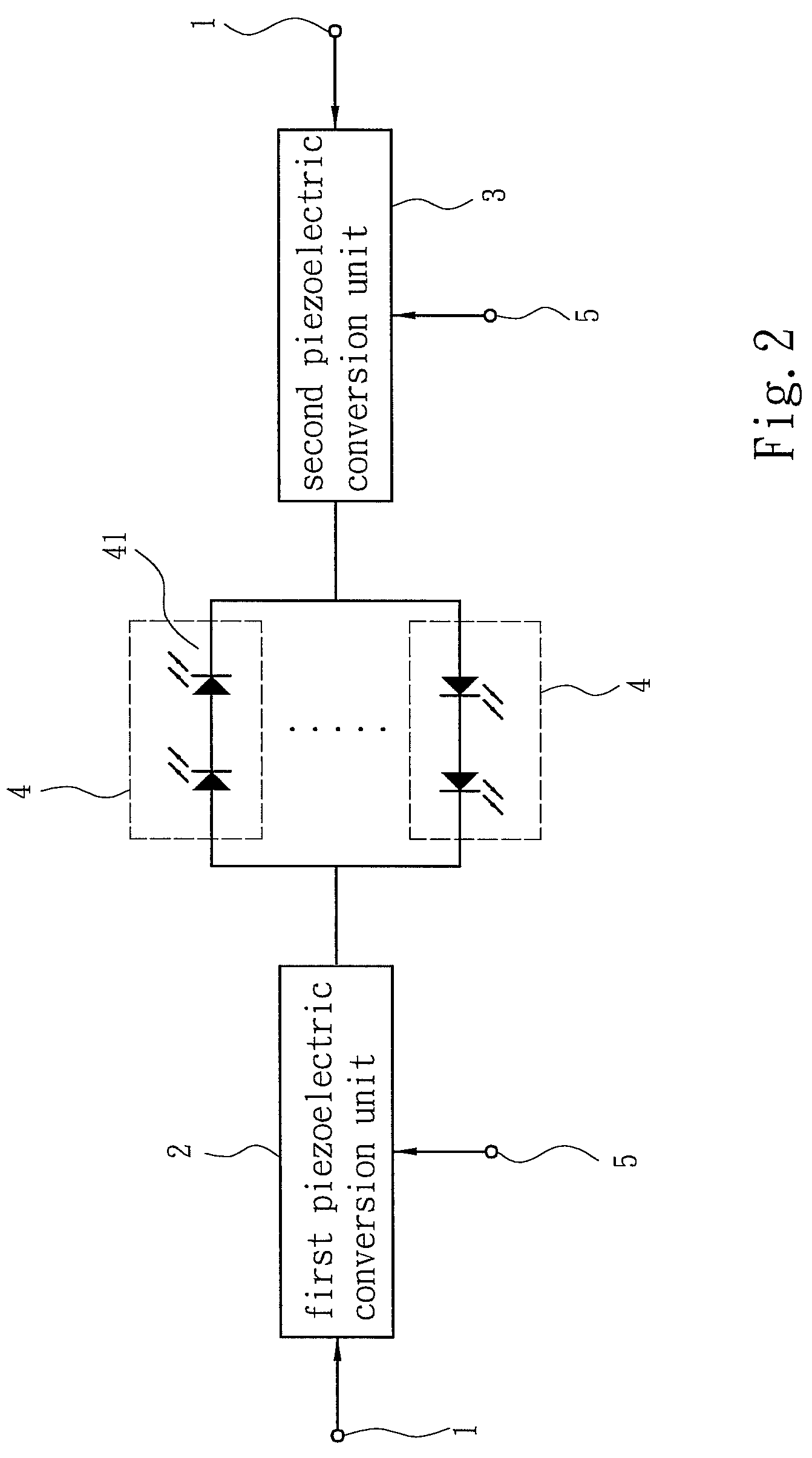
[0011]Refer to FIG. 1, a block diagram schematically showing the fundamental architecture of the present invention. The present invention proposes an LED driver structure, which uses power coming from a power source 1 to generate a constant-current power to drive a plurality of LEDs 41 (shown from FIG. 2 to FIG. 4), and which comprises: a plurality of diode groups 4 connected in parallel, a first piezoelectric conversion unit 2 and a second piezoelectric conversion unit 3, which are respectively arranged at both sides of the diode groups 4. Each of the first and second piezoelectric conversion units 2 and 3 has at least one piezoelectric inverter. The present invention utilizes the advantage of the piezoelectric effect to provide a constant-current driving power. Among the plurality of diode groups 4, at least one diode group 4 is formed of a plurality of LEDs 41...


PUM


Abstract

The present invention discloses an LED driver structure, which obtains input power coming from a power source to generate a constant-current power to drive a plurality of LEDs, and which comprises: a plurality of diode groups connected in parallel, a first piezoelectric conversion unit and a second piezoelectric conversion unit respectively arranged at both sides of the diode groups. The first and second piezoelectric conversion units receive the input power and opposite-phase convert the input power into driving powers to drive the diode groups. Among the plurality of diode groups, at least one diode group is formed of a plurality of LEDs. Each of the first and second piezoelectric conversion units has a piezoelectric inverter, which can easily achieve an impedance matching and a constant-current power to drive LEDs via a piezoelectric effect. Besides, the present invention also has the advantage of cost efficiency.

Description

FIELD OF THE INVENTION[0001]The present invention relates to an LED driver structure, wherein a transformer unit cooperates with a push-pull driving circuit to generate driving power to drive an LED group.BACKGROUND OF THE INVENTION[0002]LED (Light Emitting Diode) has advantages of small size, long lifetime, low power consumption, and high light efficiency. With the development of various colors of LEDs, LED has extensively replaced traditional light sources and has been widely used in many illumination and display applications. Therefore, many semiconductor manufacturers pay their attention to the development of LED. Similar to a general diode, LED also has forward bias and reverse bias in electric operation. In forward bias, current can easily pass through LED; in reverse bias, almost none current pass through LED. Only forward bias can make LED emit light. Thus, only the positive semi-period of alternating current can drive LED to work. However, LED has a smaller reverse breakdow...

Claims


Application Information

Patent Timeline
Patent Type & Authority Patents(United States)
IPC IPC(8): H01J7/44H01L41/00
CPCG09G3/14H05B33/0809H05B33/089G09G2310/0272G09G2330/021G09G2330/045H05B45/39H05B45/56
Inventor CHENG, YING-CHANGLIU, SHIH-HUNG
Owner ZIPPY TECH
Why Eureka
Try Eureka