Transmitting/receiving device and communication system using the same
a technology of communication system and transmission device, which is applied in the direction of generating/distributing signals, phase-modulated carrier systems, instruments, etc., can solve the problems of increasing the cost of crystal oscillators used as externally mounted components, and the use of more expensive crystal oscillators, etc., and achieve excellent adaptability
- Summary
- Abstract
- Description
- Claims
- Application Information
AI Technical Summary
Benefits of technology
Problems solved by technology
Method used
Image
Examples
embodiment 1
[0076]Embodiment 1 of the present invention will now be explained first with reference to FIGS. 1-12.
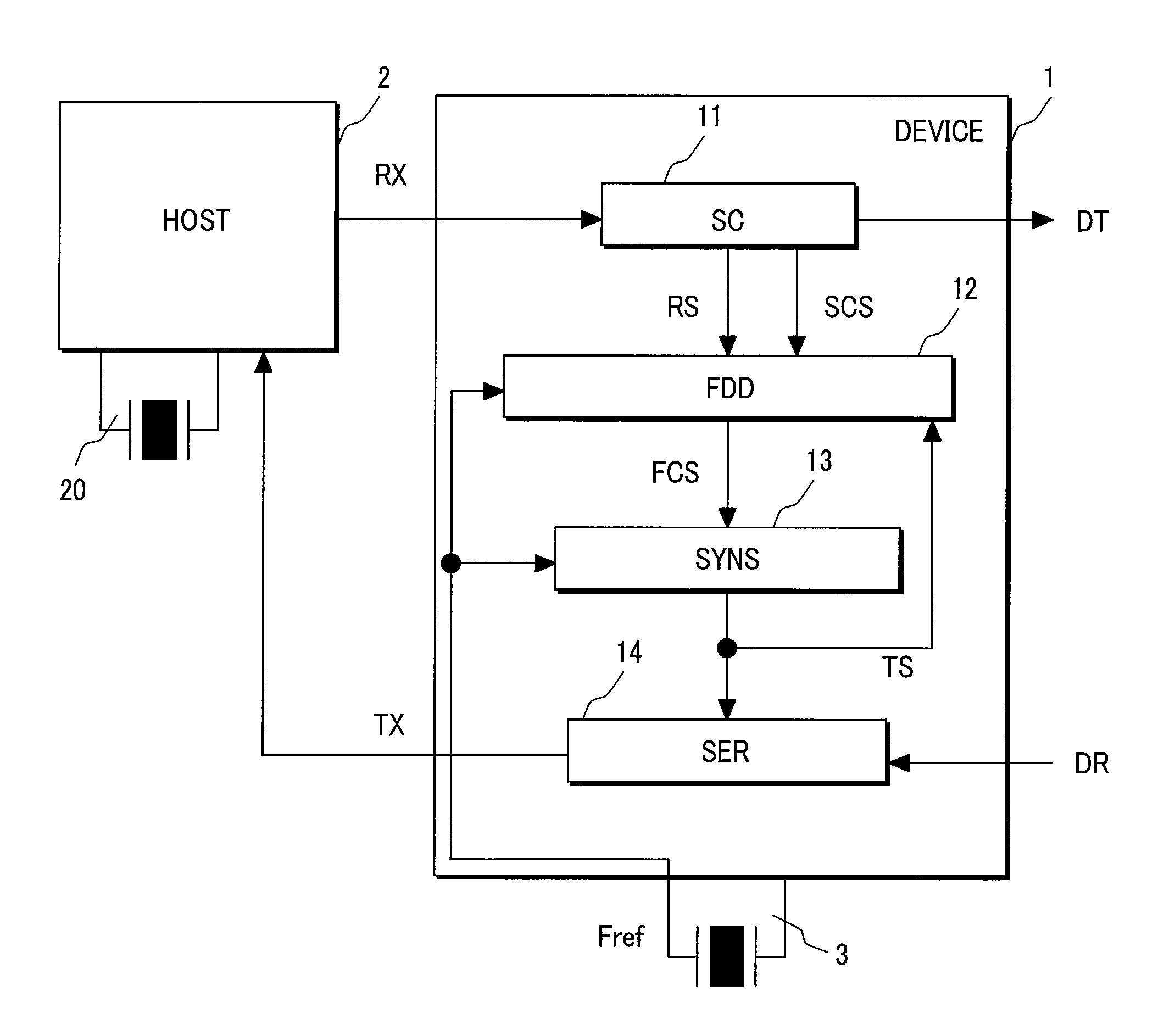
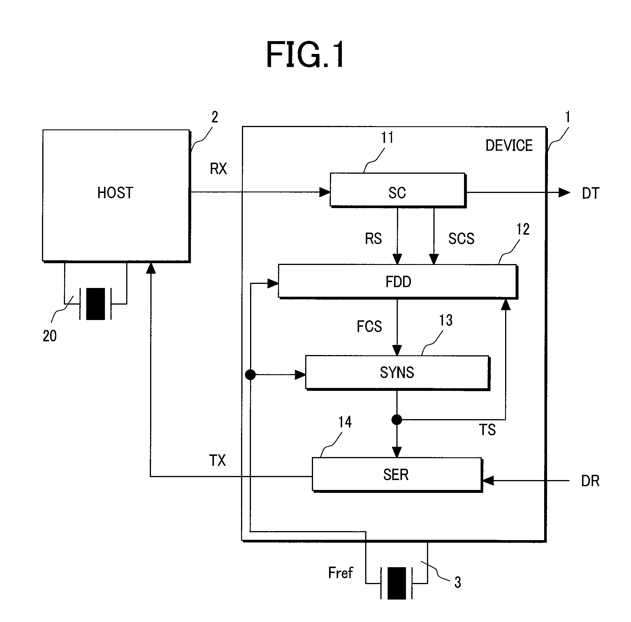
[0077]FIG. 1 is a block diagram for explaining an overall configuration of a communication system with an automatic coordination function of transmission signals.
[0078]The communication system according to this embodiment is configured to carry out bidirectional communication a device 1 provided with a transmitting / receiving device having a transmitting / receiving function and a host 2 provided with a transmitting / receiving device having a transmitting / receiving function through automatic coordination of transmission signals from each other. That is, the communication system includes the host 2 which outputs RX to the device 1 and receives TX from the device 1, the device 1 which receives RX from the host 2 and outputs a reception data DT and which receives a transmission data DR and transmits TX to the host 2, and a reference signal generating source 3 inputting a reference signal Fr...
embodiment 2
[0131]A communication system with an automatic coordination function of transmission signals according to a second embodiment of the present invention will now be explained with reference to FIGS. 13-19.
[0132]FIG. 13 is a block diagram for explaining an overall configuration of the communication system according to Embodiment 2.
[0133]The communication system in this embodiment includes a host 2 which outputs RX to a device 1 and receives TX from the device 1, the device 1 which receives RX from the host 2 and outputs a reception data DT and which receives a transmission data DR and transmits TX to the host 2, an oscillator 3 inputting a reference signal Fref to the device 1, and a transmitting / receiving device which includes a case where transmitting / receiving signal frequencies of spread spectrum (SSC) performed by serial ATA and the like are not uniform.
[0134]The device 1 includes a synchronization establishment unit 11 which is inputted the RX the device 1 received, extracts a cl...
embodiment 3
[0188]Next, a transmitting / receiving device with an automatic coordination function for transmission according to a third embodiment will be explained with reference to FIG. 22.
[0189]Embodiment 3 is a modification of Embodiment 1. That is, although Embodiment 1 utilized the oscillator 3 as a reference signal generation source, Embodiment 3 utilizes a VCO 15 and a reference voltage generation circuit (BGR) instead of the oscillator to generate a reference signal. By mounting the VCO 15 capable of generating a frequency controlled output signal with a control voltage VB generated by the BGR 16 inside the device 1, it becomes possible to generate a reference signal Fref inside the device 1. This can also be introduced as a modification of Embodiment 2. The transmitting / receiving device (not shown) of the host 2 is configured to operate based on a high-accuracy reference signal generated by a crystal oscillator for example.
[0190]For a configuration of the BGR 16 used in this embodiment,...
PUM
 Abstract
Description
Claims
Application Information
 - R&D
- Intellectual Property
- Life Sciences
- Materials
- Tech Scout
- Unparalleled Data Quality
- Higher Quality Content
- 60% Fewer Hallucinations
Browse by: Latest US Patents, China's latest patents, Technical Efficacy Thesaurus, Application Domain, Technology Topic, Popular Technical Reports.
© 2025 PatSnap. All rights reserved.Legal|Privacy policy|Modern Slavery Act Transparency Statement|Sitemap|About US| Contact US: help@patsnap.com


