Combustion chamber end wall with ventilation

a combustion chamber and end wall technology, applied in mechanical equipment, machines/engines, lighting and heating apparatus, etc., can solve the problems of undesirable heating of the end wall and high temperature, and achieve the effect of improving the insulating ability of the layer of air

Active Publication Date: 2010-09-07
SN DETUDE & DE CONSTR DE MOTEURS DAVIATION S N E C M A
View PDF22 Cites 18 Cited by
  • Summary
  • Abstract
  • Description
  • Claims
  • Application Information

AI Technical Summary

Benefits of technology

[0008]By means of these dispositions that avoid the necessarily expensive and lengthy procedure of designing a new connection system between the bowl and the deflector, both the root of the deflector and the annular portion are cooled by convection by means of a flow of air coming from outside the combustion chamber. This serves to make the temperature of the end wall more uniform by reducing heat flow by conduction by reducing contact areas at the interface and by ventilating the deflector via the bowl interface, thereby obtaining better mechanical behavior. When the bowl possesses a collar at its downstream end, the invention makes it possible to obtain more efficient cooling of the collar. In addition, removing material from the interface and providing holes produces a weight saving.
[0010]This configuration enables the air coming from outside the combustion chamber to cool the downstream portion of the deflector, thereby limiting coke deposition on the deflector.
[0011]Advantageously, the annular portion possesses an annular rib towards its downstream end, which rib is in contact with the deflector over a contact zone that constitutes the remaining portion of the interface, the annular rib being pierced by second bowl holes, the air coming from the annular cavity being capable of flowing through the second holes so as to cool the downstream end of the bowl.
[0012]This configuration enables air coming from outside the combustion chamber to cool the downstream end of the bowl by impact, and also to cool the collar by impact, if the bowl has one.
[0014]The presence of these holes enables the cooler air coming from outside the combustion chamber to flow directly between the end wall of the chamber and the deflector, and thus improve the insulating ability of the layer of air situated between the end wall and the deflector.

Problems solved by technology

Since the end wall of the combustion chamber is in the immediate proximity of the injector devices that it carries, it is subjected to high temperatures.
However that interface between the annular portion of the bowl and the root of the deflector leads to undesirable heating of the end wall by conduction via the interface.

Method used


Image

  • Combustion chamber end wall with ventilation
  • Combustion chamber end wall with ventilation
  • Combustion chamber end wall with ventilation

Examples


Embodiment Construction

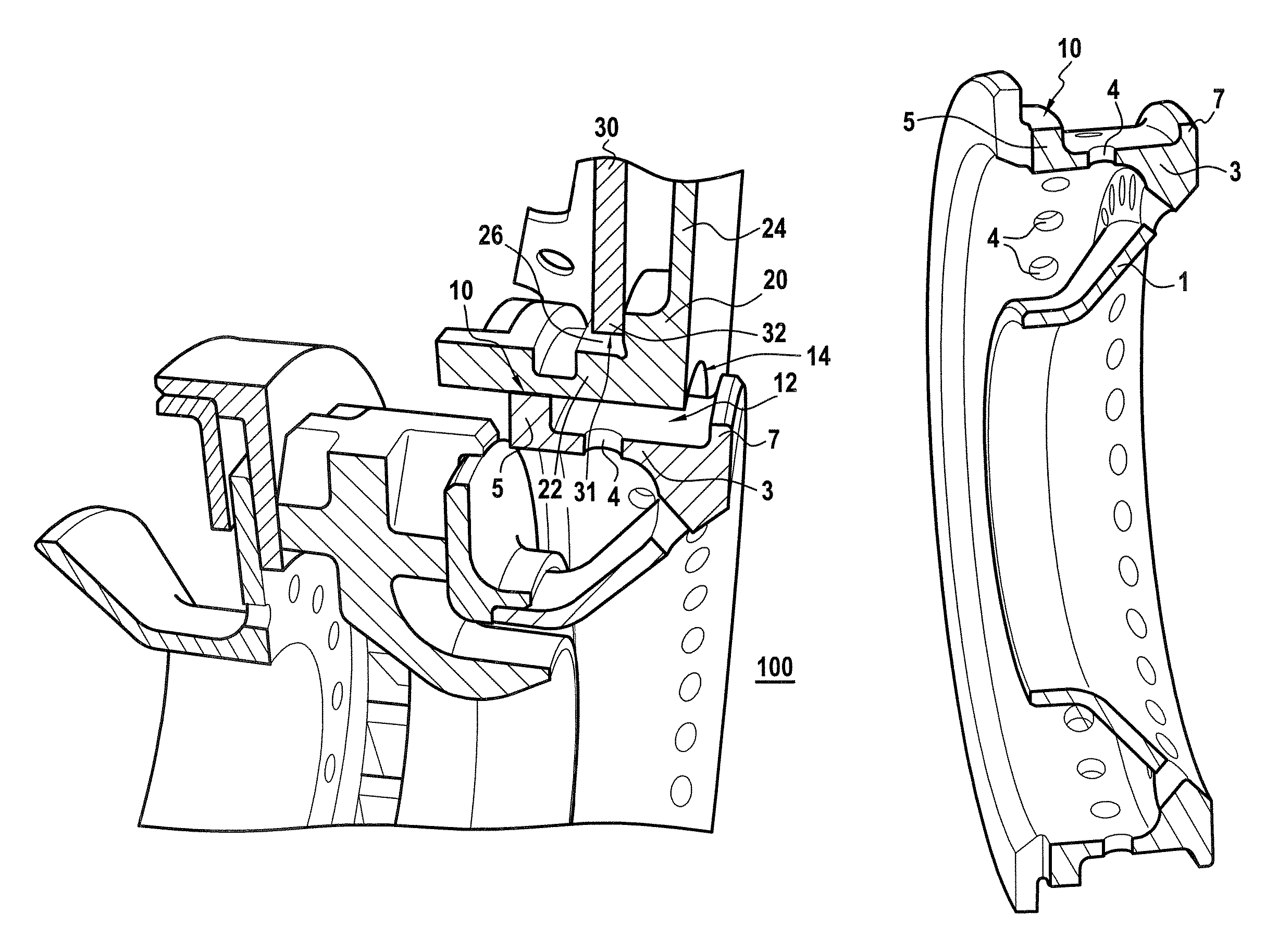
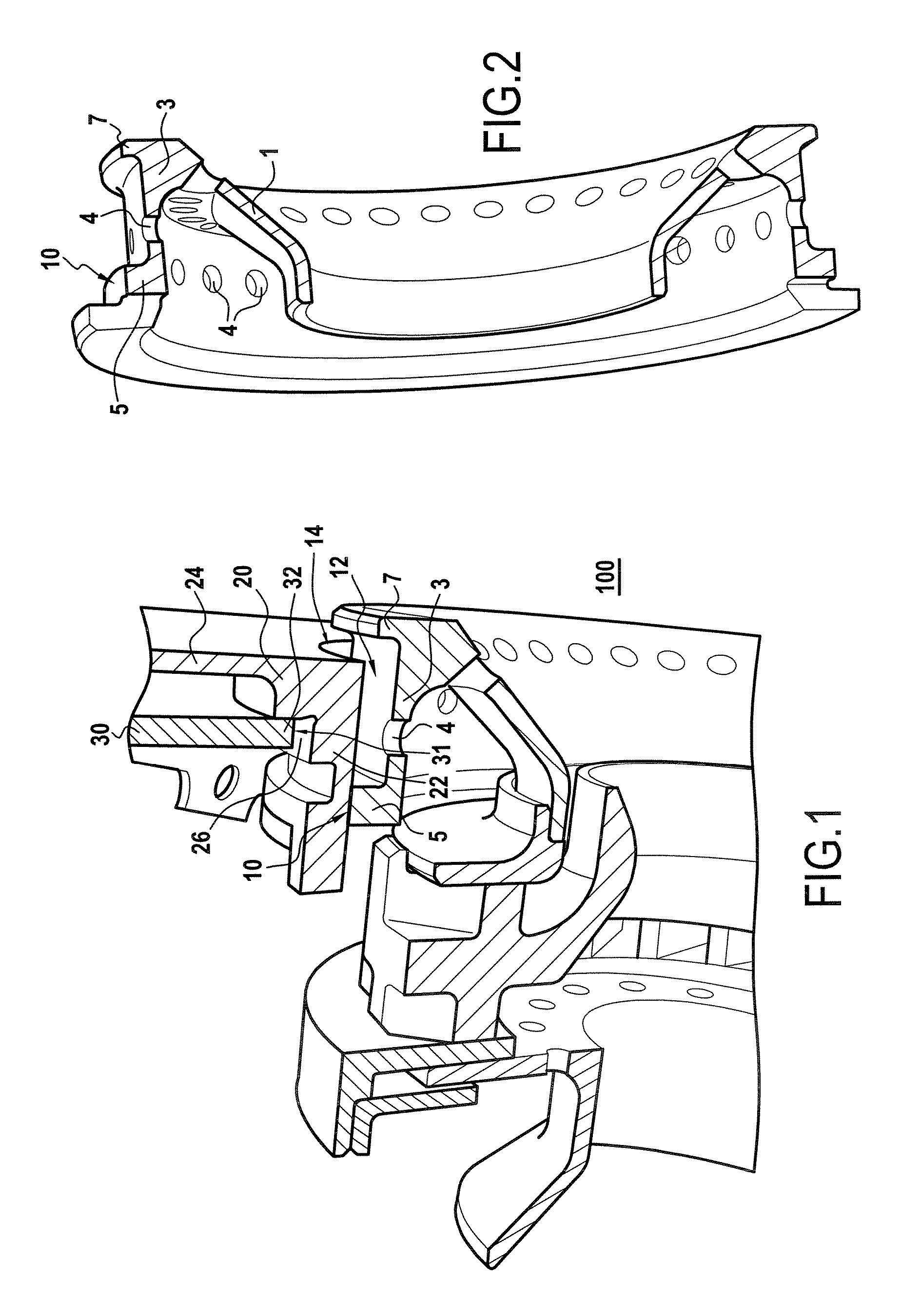
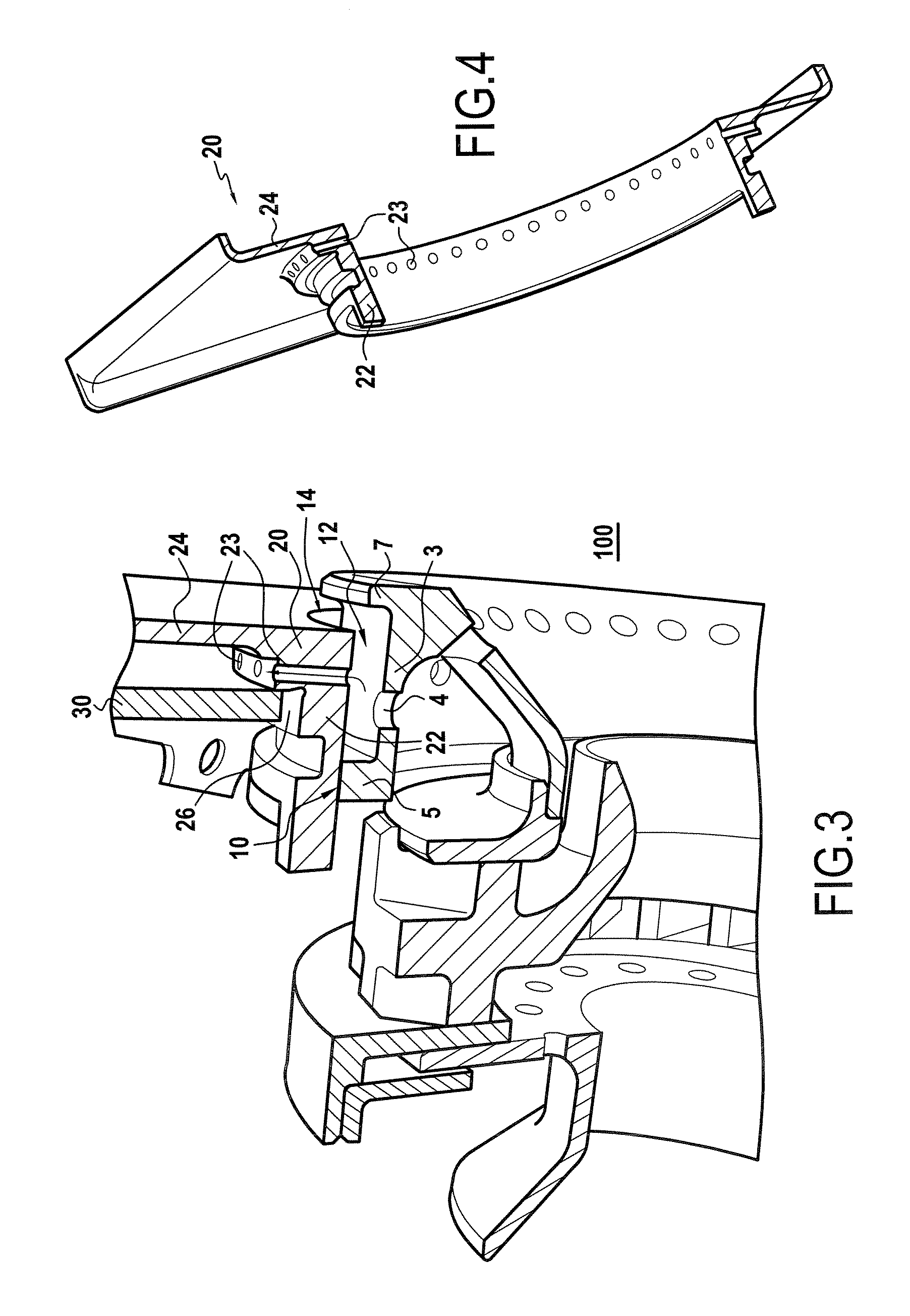
[0023]As shown in FIGS. 1 and 2, the bowl 1 possesses an annular portion 3 that extends from the downstream end of the bowl 1 in the upstream direction relative to the flow of gas. Around the bowl 1 there is attached the deflector 20 which possesses a root 22 parallel to the main axis of the bowl, and downstream from its root 22, a plane portion 24 perpendicular to the main axis of the bowl. The deflector 20 is mounted in one of the circular holes 31 in the end wall of the chamber 30. The upstream portion 5 of the annular portion 3 is in contact with the root 22 of the deflector 20 via a first annular contact zone 10 which constitutes the interface between the annular portion 3 and the deflector 20. This defines an annular cavity 12 between the annular portion 3 and the root 22 of the deflector 20. The annular cavity 12 opens out to the combustion chamber 100 via an annular orifice 14 defined by the plane downstream portion 24 of the deflector 20 and the downstream end of the annula...


PUM


Abstract

A combustion chamber having a chamber end wall that presents a plurality of air and fuel injector devices, each of the devices including a bowl and a deflector mounted on a main axis forming a heat shield disposed around the bowl which flares in the gas flow direction and possesses an annular portion, the interface between the bowl and the deflector being situated on this annular portion, at least a portion of the interface being situated towards the end of the annular portion that is downstream in the gas flow direction, such that an annular cavity is defined between the deflector and the downstream annular portion of the interface. First bowl holes are formed in the annular portion to open out facing the edge of the chamber end wall that is in contact with the deflector in order to sustain a flow of air from upstream to downstream in the annular cavity.

Description

[0001]The present invention relates to the field of combustion chambers for aviation turbomachines.[0002]The invention relates more particularly to the field of turbomachine combustion chambers of the kind having a chamber end wall that presents a plurality of air and fuel injector devices, each of said devices comprising, mounted on a main axis, a bowl and a deflector forming a heat shield disposed around said bowl, said bowl being flared in the gas flow direction and possessing an annular portion, the interface between said bowl and said deflector being situated on said annular portion.BACKGROUND OF THE INVENTION[0003]In a combustion chamber of a turbomachine, a combustion reaction occurs between the fuel and the oxygen of the air. This results in the hot gas produced by the combustion being expelled at high speed, which gas delivers thrust on expanding. It is this thrust that serves, for example, to propel an airplane fitted with one or more turbomachines. Typically, a combustion...

Claims


Application Information

Patent Timeline
Patent Type & Authority Patents(United States)
IPC IPC(8): F02C1/00F02G3/00
CPCF23R3/283F23R3/60F23R3/10F23R2900/03044Y02T50/675F23R2900/00012Y02T50/60
Inventor BIEBEL, ROMAINGAUTIER, CLAUDESANDELIS, DENIS JEAN MAURICE
Owner SN DETUDE & DE CONSTR DE MOTEURS DAVIATION S N E C M A
Why Eureka
Try Eureka