Method of cleaning UV irradiation chamber

a technology of ultraviolet light and irradiation chamber, which is applied in the direction of cleaning hollow objects, cleaning using liquids, lighting and heating apparatus, etc., can solve the problem of short maintenance cycle (the number of processings and processing time required before the transmission window is cleaned or replaced) and achieves the effect of longer cleaning time and high efficiency

Active Publication Date: 2010-09-07
ASM JAPAN
View PDF166 Cites 382 Cited by
  • Summary
  • Abstract
  • Description
  • Claims
  • Application Information

AI Technical Summary

Benefits of technology

[0009]Traditionally, the method of introducing O2 to the reaction space and irradiating UV to generate ozone, thereby removing the deposits by means of the generated ozone, has been used in general. However, other methods offering higher efficiency are being sought in light of the longer cleaning time required in the cure process where a large amount of outgas generates.

Problems solved by technology

However, UV light that generates high energy tends to cause a drop in transmission factor depending on the material of the transmitted window and also due to deposits accumulating on the window material, and therefore the maintenance cycle (number of processings and processing time required before the transmitted window is cleaned or replaced) must be set very short in the cure process where a large amount of outgas (cracked gas generated by the irradiated film) generates.

Method used


Image

  • Method of cleaning UV irradiation chamber
  • Method of cleaning UV irradiation chamber
  • Method of cleaning UV irradiation chamber

Examples


Embodiment Construction

[0021]The invention will be explained further with reference to specific embodiments, but the specific embodiments are not intended to limit the present invention.

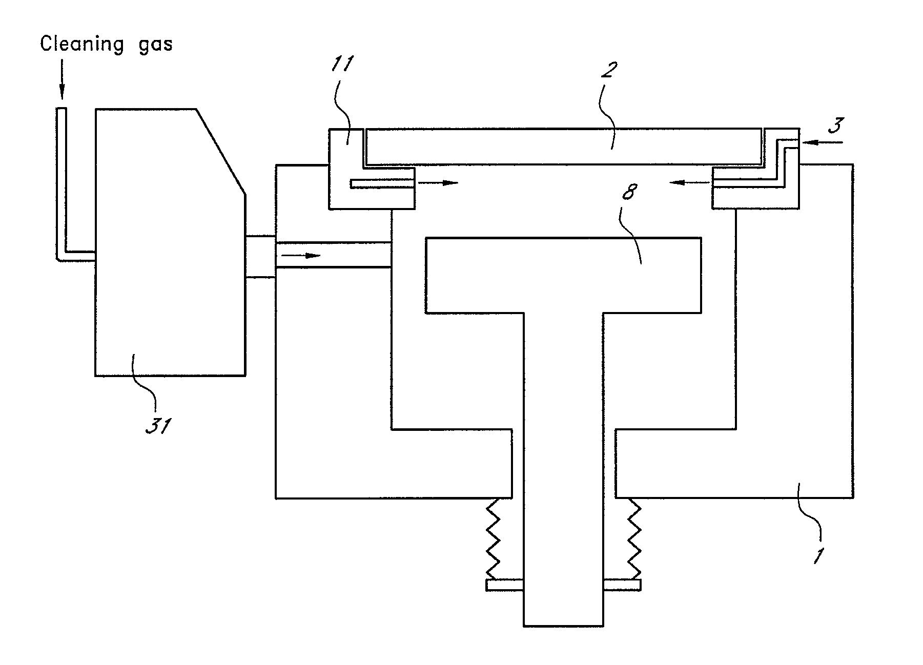
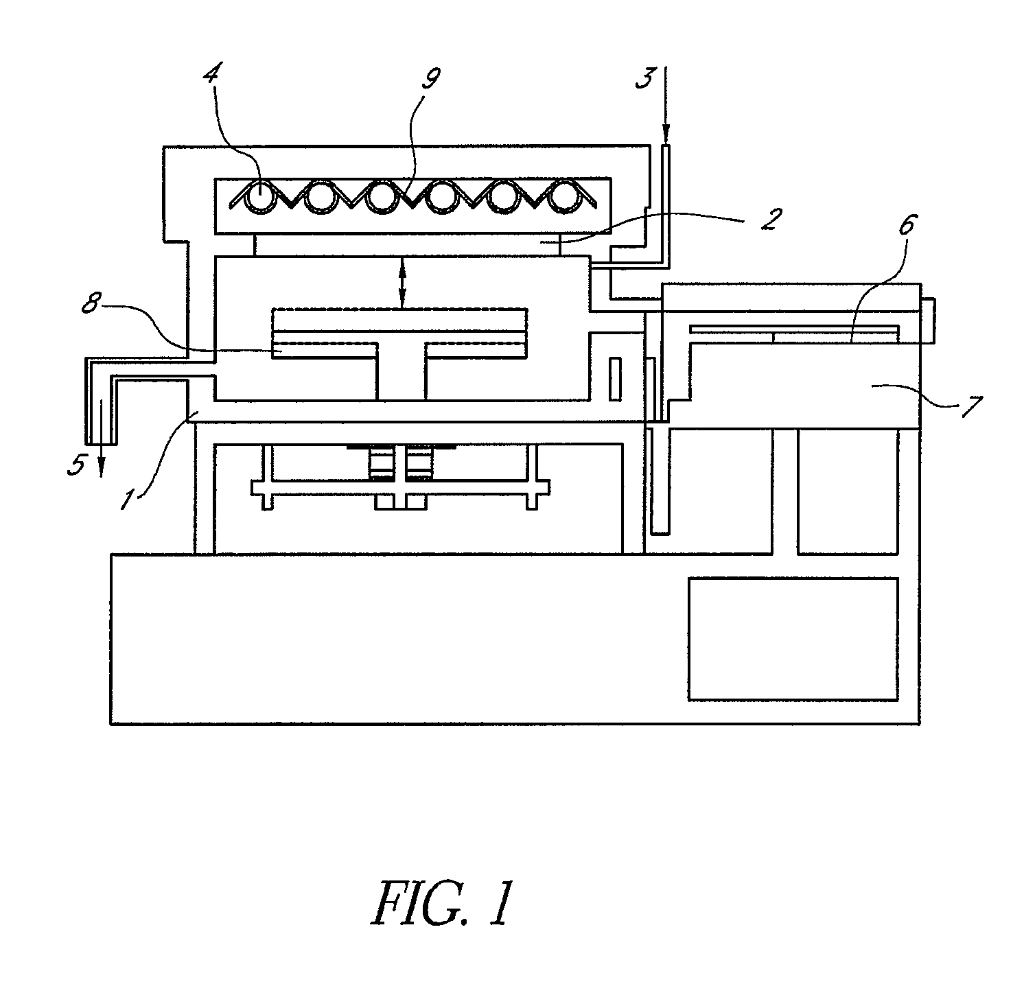
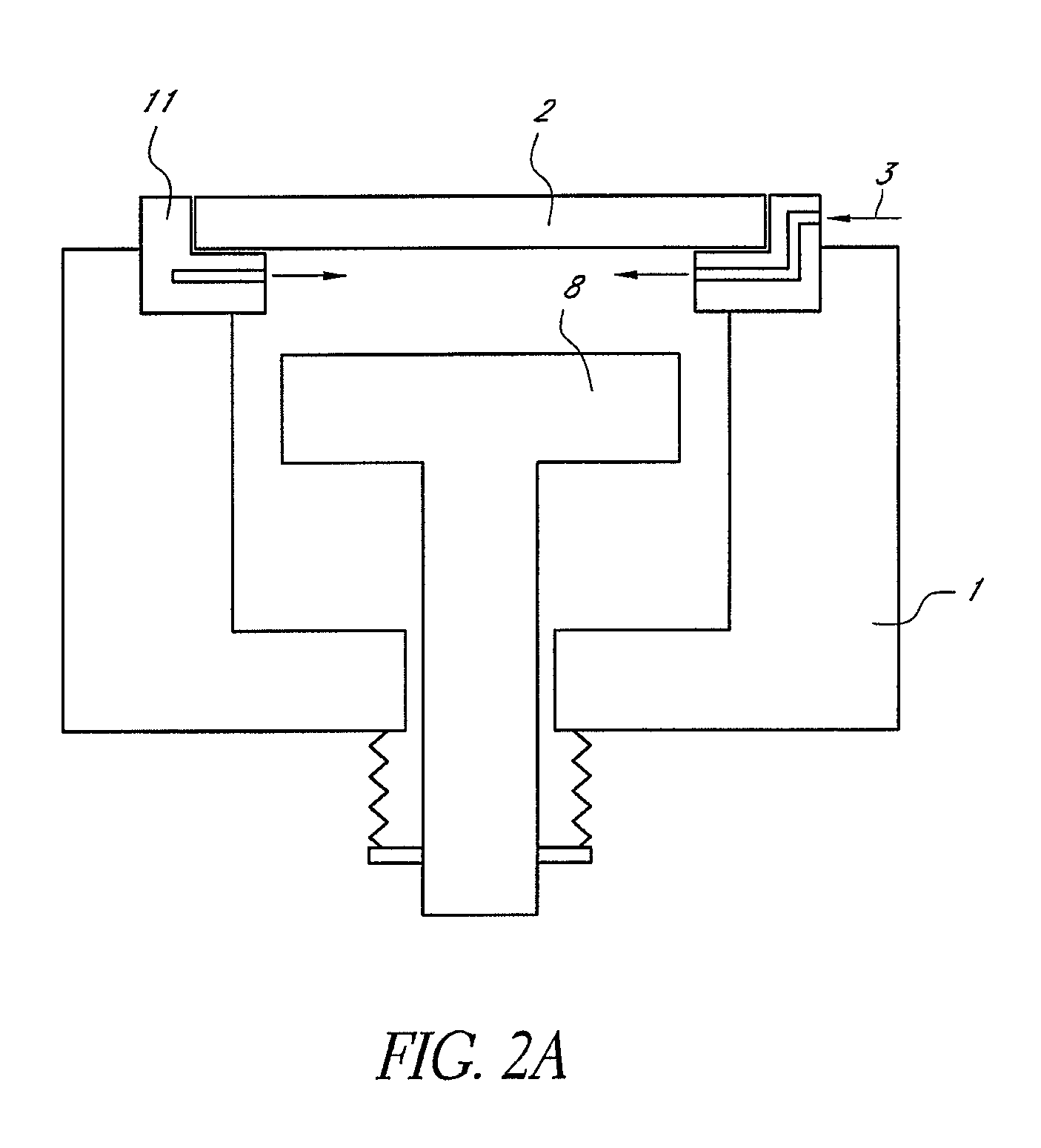
[0022]In an embodiment, the present invention provides a method of cleaning a UV irradiation chamber comprising steps of: (i) after completion of irradiating a substrate with UV light transmitted through an optical transmitted window provided in the UV irradiation chamber, generating radical species of a cleaning gas outside the UV irradiation chamber; and (ii) introducing the radical species from the outside of the UV irradiation chamber into the UV irradiation chamber, thereby cleaning the optical transmitted window.

[0023]The UV irradiation process can be any suitable processes including those disclosed in U.S. Pat. Nos. 6,759,098 and 6,296,909, the disclosure of which is incorporated herein by reference in their entirety. Typically, the process may comprise processing a substrate (e.g., a semiconductor substrate) placed...


PUM

PropertyMeasurementUnit
wavelengthaaaaaaaaaa

Abstract

A method of cleaning a UV irradiation chamber includes steps of: (i) after completion of irradiating a substrate with UV light transmitted through an optical transmitted window provided in the UV irradiation chamber, generating radical species of a cleaning gas outside the UV irradiation chamber; and (ii) introducing the radical species from the outside of the UV irradiation chamber into the UV irradiation chamber, thereby cleaning the optical transmitted window.

Description

CROSS-REFERENCE TO RELATED APPLICATIONS[0001]This application claims the benefit of U.S. Provisional Application No. 60 / 845,732, filed Sep. 19, 2006, the disclosure of which is herein incorporated by reference in its entirety.BACKGROUND OF THE INVENTION[0002]1. Field of the Invention[0003]The present invention generally relates to semiconductor-processing by ultraviolet (UV) radiation and cleaning of a ultraviolet (UV) radiation chamber for semiconductor-processing, particularly cleaning of an optical transmitted window provided in a UV irradiation chamber.[0004]2. Description of the Related Art[0005]Traditionally, UV processing apparatuses have been used in general in the property modification of various processing targets by means of UV light as well as in the production of substances that utilize photochemical reaction. With the trend for higher integration of devices in recent years, wiring designs are becoming finer and multi-layer wiring structures are being adopted, which in ...

Claims


Application Information

Patent Timeline
Patent Type & Authority Patents(United States)
IPC IPC(8): B08B7/04
CPCB08B7/0057C23C16/4405C23C16/452C23C16/482Y10S134/902
Inventor MATSUSHITA, KIYOHIROFUKUDA, HIDEAKIKAGAMI, KENICHI
Owner ASM JAPAN
Why Eureka
Try Eureka