Compression encoder, compression encoding method and program

a compression encoder and encoder technology, applied in the field of compression encoders and compression encoders, can solve the problems of low immediacy and large number of operations, and achieve the effects of maintaining image quality, minimal operations, and high speed

Inactive Publication Date: 2010-09-07
MEGACHIPS
View PDF3 Cites 10 Cited by
  • Summary
  • Abstract
  • Description
  • Claims
  • Application Information

AI Technical Summary

Benefits of technology

[0025]This allows a compressed image to be readily generated that meets a target rate while maintaining image quality of a region of interest. Further, processing can be achieved by the Max-shift method provided for a conventional compression encoder which is specified as an optional function of JPEG2000.
[0027]This allows a compressed image to be readily generated that meets a target rate while maintaining image quality of a region of interest. Further, processing can be achieved by a conventional compression encoder not provided with the Max-shift method which is specified as an optional function of JPEG2000.
[0029]This achieves high speed processing with minimal operations as compared with conventional techniques which require processes for estimating an optimal solution while controlling a data compression ratio in quantization according to target image quality.
[0037]This allows a compressed image to be generated with high display image quality in consideration of the human visual characteristics.
[0039]This provides a device for performing quantization efficiently according to target image quality.
[0041]This allows a compressed image to be generated efficiently while maintaining image quality that meets a target rate.

Problems solved by technology

This method, however, arises problems of: (1) requiring calculating the amount of distortion for each rate in each coding pass, and the optimal solution for a certain coding rate has to be estimated, resulting in a great number of operations and low immediacy; and (2) requiring providing a memory for storing the amount of distortion calculated in each coding pass.

Method used


Image

  • Compression encoder, compression encoding method and program
  • Compression encoder, compression encoding method and program
  • Compression encoder, compression encoding method and program

Examples


first preferred embodiment

Compression Encoder

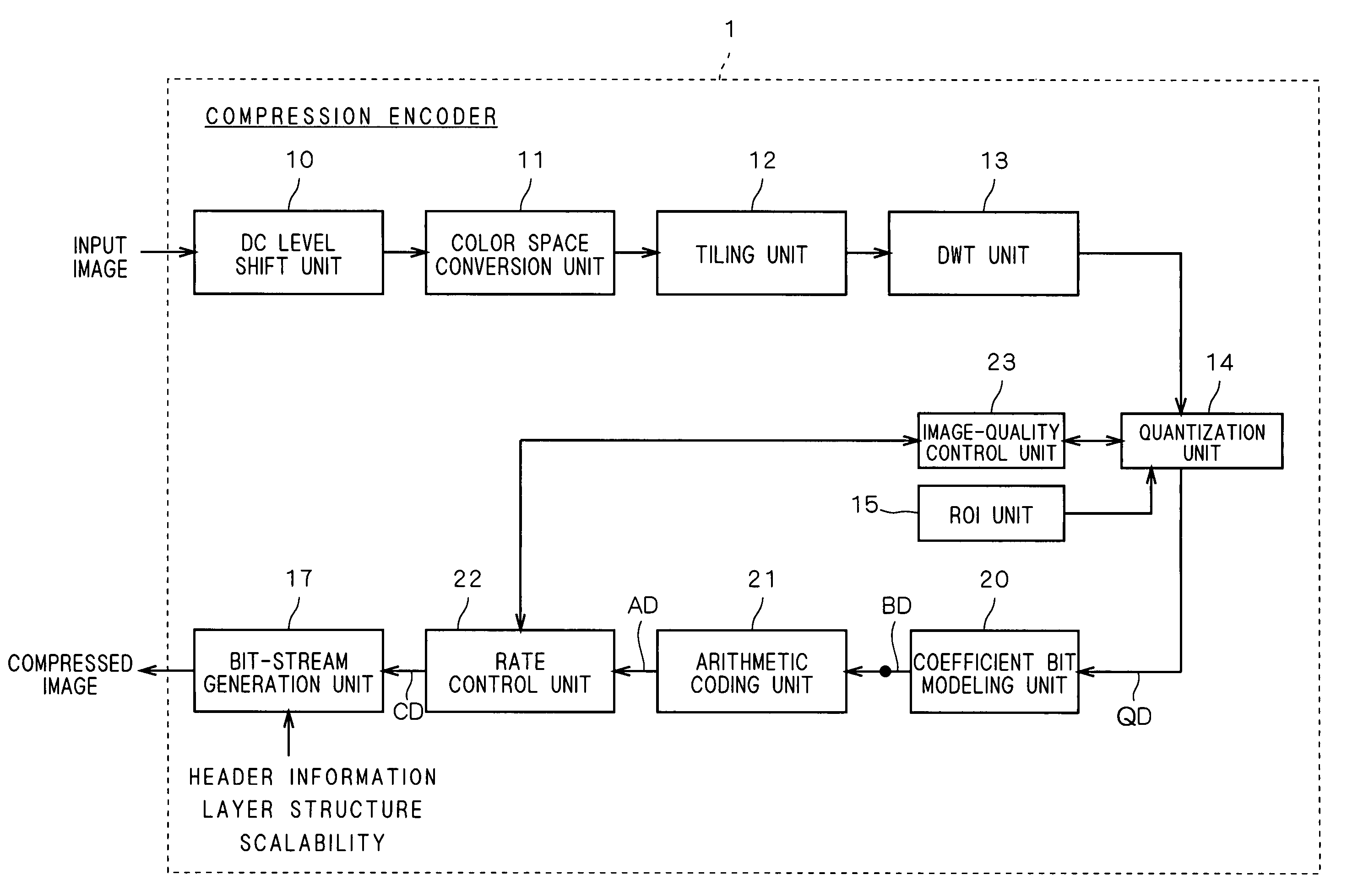
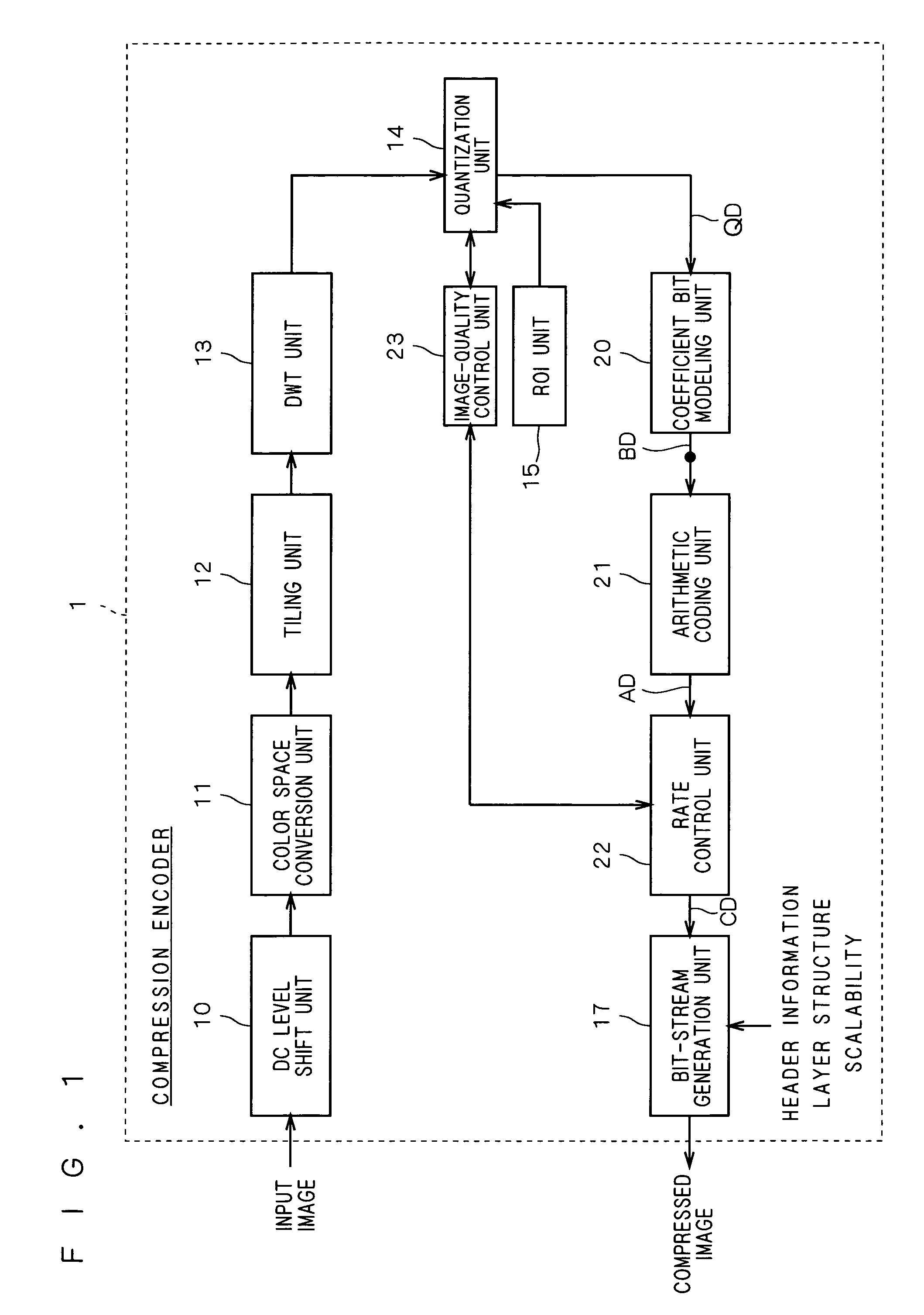
[0071]FIG. 1 is a functional block diagram showing a general configuration of a compression encoder 1 according to a first preferred embodiment of the present invention. After general description of the configuration and function of this compression encoder 1, quantization and coding techniques according to this preferred embodiment will be described in detail.

[0072]The compression encoder 1 comprises a DC level shift unit 10, a color-space conversion unit 11, a tiling unit 12, a DWT unit 13, a quantization unit 14, a ROI unit 15, a coefficient bit modeling unit 20, an arithmetic coding (entropy coding) unit 21, a rate control unit 22, an image-quality control unit 23 and a bit-stream generation unit 17.

[0073]All or parts of the units 10 to 15, 17 and 20 to 23 in the compression encoder 1 may consist of hardware or programs that run on a microprocessor.

[0074]An image signal inputted to the compression encoder 1 is DC level shifted in the DC level shift unit 10 as ...

second preferred embodiment

[0200]According to the first preferred embodiment, at the stage of quantization, data is sorted and bit shifted based on the quantization step size, and sorted and bit shifted based on ROI information.

[0201]In contrast, according to this second preferred embodiment, the quantization unit 14 only performs quantization based on the ROI information. Then, after being outputted from the quantization unit 14 and entropy coded on a block-by-block basis in the coefficient bit modeling unit 20 and arithmetic coding unit 21, data is sorted and bit shifted with the quantization step size, and sorted and bit shifted based on the ROI information, in the rate control performed by the rate control unit 22.

[0202]Hereinbelow, the configuration and operation of a compression encoder according to the present embodiment is described, particularly directing to differences from the first preferred embodiment.

Compression Encoder

[0203]FIG. 18 is a functional block diagram showing a general configuration o...

third preferred embodiment

[0239]According to the present invention as previously described in the first preferred embodiment, an image signal is not always necessarily divided into tiles in the tiling unit 12, and instead a single frame of image signal may be outputted as-is to a functional block subsequent to the tiling unit 12. Accordingly, the first and second preferred embodiments have described performing quantization and rate control without such tiling.

[0240]In contrast, this third preferred embodiment is implemented by performing tiling before quantization as well as performing rate control based on ROI information set in each tile. Hereinbelow, the procedure of compression and coding in the case of performing tiling is described, particularly directing to differences from the first and second preferred embodiments.

Compression Encoder

[0241]A compression encoder according to the present embodiment has a similar configuration to that of the second preferred embodiment shown in FIG. 18, and redundant ex...


PUM


Abstract

A DWT unit applies wavelet transform to an input image signal to output transform coefficients, and on those transform coefficients, a quantization unit performs quantization, sorting and bit shifting with a quantization step size determined by target image quality in an image-quality control unit as well as sorting and bit shifting based on information on a region of interest specified by a ROI unit. A coefficient bit modeling unit applies bit modeling on transform coefficients outputted from the quantization unit on a bit-plane-by-bit-plane basis, and an arithmetic coding unit applies arithmetic coding on coded data inputted from the coefficient bit modeling unit. Then, a rate control unit controls the rate of coded data inputted from the arithmetic coding unit.

Description

BACKGROUND OF THE INVENTION[0001]1. Field of the Invention[0002]The present invention relates to a compression encoder and compression encoding method for use in image compression and expansion technology.[0003]2. Description of the Background Art[0004]As a next-generation high-efficiency coding standard for image data, the International Organization for Standardization (ISO) and the International Telecommunication Union-Telecommunication Standardization Sector (ITU-T) have been developing the Joint Photographic Experts Group 2000 (JPEG2000) standard. The JPEG2000 standard provides functions superior to the Joint Photographic Experts Group (JPEG) standard which is currently in the mainstream, and features the adoption of discrete wavelet transform (DWT) for orthogonal transformation and of a technique called “Embedded Block Coding with Optimized Truncation” (EBCOT) which performs bit-plane coding, for entropy coding.[0005]FIG. 25 is a functional block diagram showing a general confi...

Claims


Application Information

Patent Timeline
Patent Type & Authority Patents(United States)
IPC IPC(8): G06K9/36H03M7/30H03M7/40H04N1/41H04N19/00H04N19/126H04N19/132H04N19/136H04N19/146H04N19/147H04N19/167H04N19/176H04N19/186H04N19/189H04N19/196H04N19/20H04N19/33H04N19/34H04N19/60H04N19/63H04N19/91
CPCH04N19/647H04N19/63H04N19/645H04N19/186H04N19/162H04N19/17H04N19/127H04N19/124
Inventor MIZUNO, YUSUKE
Owner MEGACHIPS
Why Eureka
Try Eureka