Systems and methods for generating data based on one or more spectrally-encoded endoscopy techniques

a technology of generating data and endoscopy, applied in the field of system and method for generating data, can solve the problems of difficult depth resolution imaging with a large three-dimensional field of view, increased size, cost, complexity of such devices, etc., to achieve the effect of facilitating high-speed imaging, removing height ambiguity, and improving snr

Active Publication Date: 2010-09-14
THE GENERAL HOSPITAL CORP
View PDF477 Cites 50 Cited by
  • Summary
  • Abstract
  • Description
  • Claims
  • Application Information

AI Technical Summary

Benefits of technology

[0024]The exemplary embodiment of the SD-SEE system can perform 3D imaging, e.g., at about 30 frames per second, with SNR of greater than about 30 dB. Using an exemplary high-speed line camera in a high-resolution spectrometer, e.g., each x-z plane can be captured in a single shot. This exemplary embodiment of the present invention facilitates high-speed imaging with two to three orders of magnitude improvement in SNR over conventional techniques. In one further exemplary embodiment of the present invention, the path length control device of the reference arm can include an RSOD, and real-time 3D imaging of tissue can be facilitated at a rate of about 30 frames per second with an SNR typically of about 30 dB. SNR of greater than about 30 dB can provide an improvement of about two to three orders of magnitude over time-domain SEE techniques.
[0025]In a further exemplary embodiment of the present invention, a detection SEE technique can be provided which uses spectral-domain interferometry. For example, a light or other electro-magnetic radiation can be provided to a sample and a reference arm. A path length of the reference arm can be changed, spectral interference between light reflected from the sample and light reflected from the reference arm may be measured, and a cross-correlation between a short time Fourier transforms (STFTs) of adjacent sample locations can be determined.
[0026]Using this exemplary arrangement according to one exemplary embodiment of the present invention, it is possible to resolve a depth ambiguity in SD-SEE. By determining a cross-correlation between STFTs of adjacent sample locations, the sign of an offset of the first cross-correlation maximum can be used to remove height ambiguity. The implementation of this exemplary cross-correlation technique can be accomplished by, e.g., stepping the sample arm slow scan axis to one location, acquiring one spectral scan, stepping the reference arm path length, and acquiring an additional spectral scan. This exemplary procedure may be repeated for the entire volumetric image. For example, moving either the sample arm or the reference path in small steps may be challenging at high speeds. Thus, according certain exemplary embodiments, the reference arm can be continuously scanned at a slow rate. The sample arm can also be continuously scanned and spectral data can be over-sampled by capturing a plurality of spectrally-encoded lines per resolution element, which can be determined by the numerical aperture of the SEE probe lens.

Problems solved by technology

Depth resolved imaging with a large, three-dimensional field of view is, however, challenging when utilizing flexible imaging probes such as borescopes, laparoscopes, and endoscopes having relatively small diameters.
The 3D field of view for these devices, however, may be limited to less than a few millimeters due to the small clear aperture of the objective lens and low f-number required for high-resolution optical sectioning.
These techniques, however, likely a large number of pieces of hardware for the probe than confocal imaging through a fiber bundle.
This additional hardware increased the size, cost, and complexity of such devices.
One problem with this exemplary approach, however, may be that the reference mirror should be maintained in a stationary configuration to within an optical wavelength during a single image (or line) acquisition time to avoid the loss of fringe visibility.
Stepping the reference mirror with such high fidelity over multiple discrete depths is quite challenging at the high rates required for real-time volumetric imaging.
For fast imaging rates and low illumination powers used for safe clinical imaging, maintaining a high SNR may be challenging.
Using an exemplary SEE technique, a low NA collection system can be utilized to achieve a large working distance, likely resulting in a decrease in the solid angle of collection of light scattered from tissue.

Method used


Image

  • Systems and methods for generating data based on one or more spectrally-encoded endoscopy techniques
  • Systems and methods for generating data based on one or more spectrally-encoded endoscopy techniques
  • Systems and methods for generating data based on one or more spectrally-encoded endoscopy techniques

Examples


Embodiment Construction

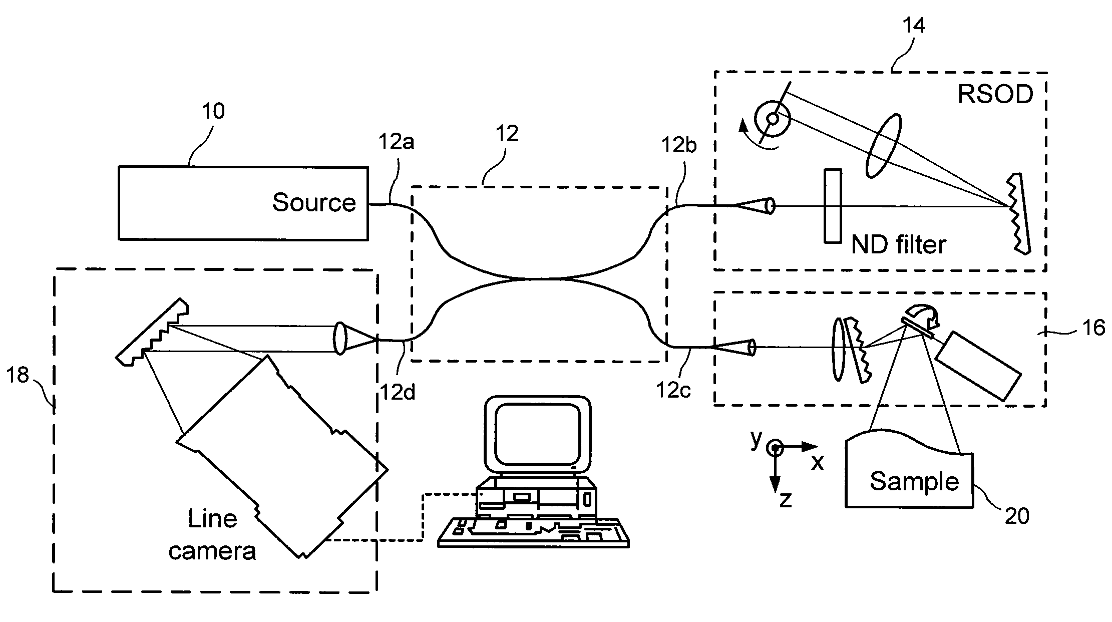
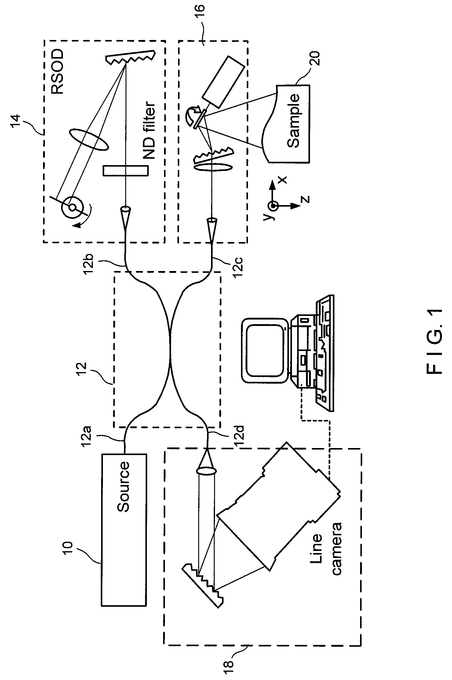
[0055]FIG. 1 shows a block diagram of an exemplary embodiment of a system according to the present invention for spectral-domain spectrally-encoded endoscopy (“SD-SEE”). This exemplary system includes a light source 10 coupled to a first port 12a of a single-mode fiber optic interferometer 12. In one exemplary embodiment, the light source 10 may be, for example, a broad-bandwidth titanium-sapphire laser of the type manufactured by, e.g., Femtolasers Produktions, GmbH, Femtosource integral OCT™, with a center wavelength of about 800 nanometers (nm) and an FWHM bandwidth of about 140 nm. Further, according to another exemplary embodiment, the interferometer 12 may be a 50 / 50 Michelson interferometer.

[0056]A second port 12b of the interferometer 12 of the system of FIG. 1 can be coupled to a reference arm which may include, e.g., an arrangement for adjusting or otherwise controlling a path length 14 coupled thereto. A third port 12c of the interferometer 12 can be coupled to a sample a...


PUM

PropertyMeasurementUnit
phase-sensitive depth measurementaaaaaaaaaa
FWHM bandwidthaaaaaaaaaa

Abstract

Exemplary systems and methods for generating data associated with at least one portion of a sample can be provided. For example, according to one exemplary embodiment of such systems and methods, it is possible to provide a particular radiation using at least one first arrangement. The particular radiation can include at least one first electro-magnetic radiation directed to at least one sample and at least one second electro-magnetic radiation directed to a reference arrangement. The first radiation and / or the second radiation can comprise a plurality of wavelengths. The first electro-magnetic radiation can be spectrally dispersed along at least one portion of the sample. The second electro-magnetic radiation measured at two or more different lengths of the reference arrangement with respect to the first arrangement. Data can be generated which is associated with the first and second electro-magnetic radiations obtained at the two different lengths using at least one second arrangement which comprises a spectrometer arrangement.

Description

CROSS-REFERENCE TO RELATED APPLICATION(S)[0001]This application is based upon and claims the benefit of priority from U.S. Patent Application Ser. No. 60 / 757,569, filed Jan. 10, 2006, the entire disclosure of which is incorporated herein by reference.STATEMENT REGARDING FEDERALLY SPONSORED RESEARCH[0002]The invention was made with the U.S. Government support under Contract No. BES-0086709 awarded by the National Science Foundation. Thus, the U.S. Government has certain rights in the invention.FIELD OF THE INVENTION[0003]The present invention generally relates to systems and methods for generating data associated with at least one portion of a sample, and particularly for, e.g., generating such data using one or more spectrally-encoded endoscopy techniques.BACKGROUND OF THE INVENTION[0004]As is known in the art, three-dimensional (3D) endoscopy which provides clinicians with depth information can greatly aid a variety of minimally invasive procedures. Depth resolved imaging with a la...

Claims


Application Information

Patent Timeline
Patent Type & Authority Patents(United States)
IPC IPC(8): G01B9/02G01J3/45G01N21/00
CPCA61B5/0066A61B5/6852G01N21/359G01N21/4795G01B9/02037G01B9/02044G01B9/02002G01B9/02091G01B9/02036A61B5/7257A61B5/726G01N2021/1787G01N2021/3595G01N2021/1782
Inventor YELIN, DVIRYUN, SEOK-HYUNBOUMA, BRETT EUGENETEARNEY, GUILLERMO J
Owner THE GENERAL HOSPITAL CORP
Why Eureka
Try Eureka