Wheel ground-contact state judging device and method

a technology for ground contact state and judging device, which is applied in the direction of tractors, instruments, cycle equipment, etc., can solve the problem of difficulty in high-precision judging of the ground-contact state of the wheels, and achieve the effect of higher precision

Active Publication Date: 2010-09-14
SUBARU CORP
View PDF36 Cites 14 Cited by
  • Summary
  • Abstract
  • Description
  • Claims
  • Application Information

AI Technical Summary

Benefits of technology

[0008]Another object of the present invention is to perform motion state control of a vehicle with high precision.
[0016]According to the present invention, the forces acting on the wheels are directly detected by the detector. When the wheel ground-contact state is bad, the force detected by the detector and the actual force are not matched with each other in value. Therefore, the wheel ground-contact state can be judged by comparing both the values. Furthermore, in this embodiment, since the force acting on the wheel is directly detected, the wheel ground-contact state properly reflects the value concerned. Therefore, the judgment of the ground-contact state can be performed with higher precision.

Problems solved by technology

However, in the method of estimating the ground-contact state of the wheel on the basis of the roll state of the vehicle, the ground-contact state of the vehicle is indirectly estimated, and thus it is difficult to judge the ground-contact state of the wheels with high precision.

Method used


Image

  • Wheel ground-contact state judging device and method
  • Wheel ground-contact state judging device and method
  • Wheel ground-contact state judging device and method

Examples


first embodiment

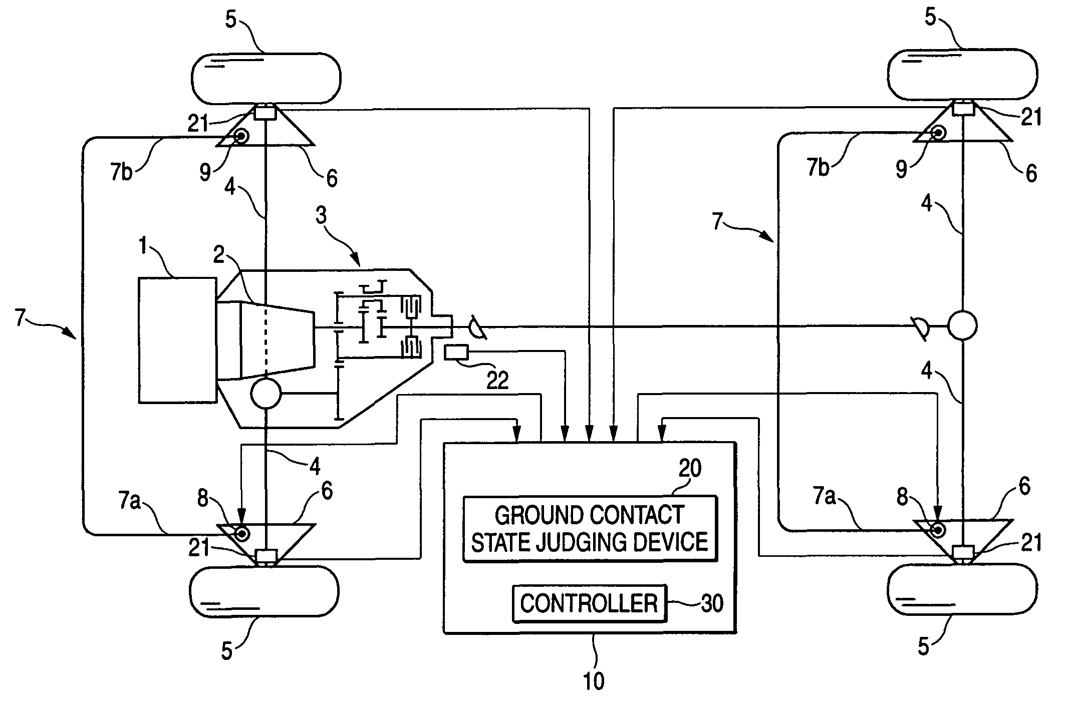
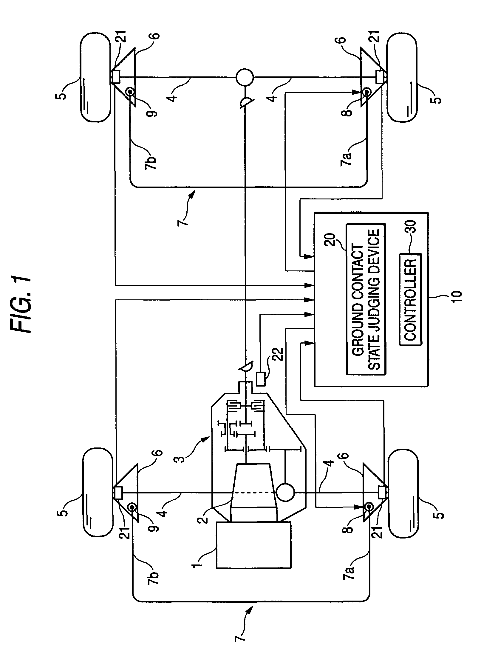
[0023]FIG. 1 is a diagram showing a vehicle to which a vehicle motion control device of the first embodiment is applied. The vehicle is a four-wheel drive vehicle which is driven by front and rear wheels. The driving force transmitted from a crank shaft (not shown) of an engine 1 is transmitted through an automatic transmission 2 and a center differential device 3 to the driving shaft (axle) 4 of each of the front wheel side and the rear wheel side. When the driving force is transmitted to the axles 4, rotational torque is applied to each wheel 5, whereby a driving force occurs in each wheel 5.

[0024]The wheels 5 are suspended from the vehicle by suspension devices provided to the front and rear wheel sides. Each suspension device mainly comprises a pair of suspension arms 6, a pair of damper cylinders (not shown), and a pair of coil springs (not shown), and they suspend the right and left wheels 5 from the vehicle. Each suspension device is provided with a stabilizer 7 having a func...

second embodiment

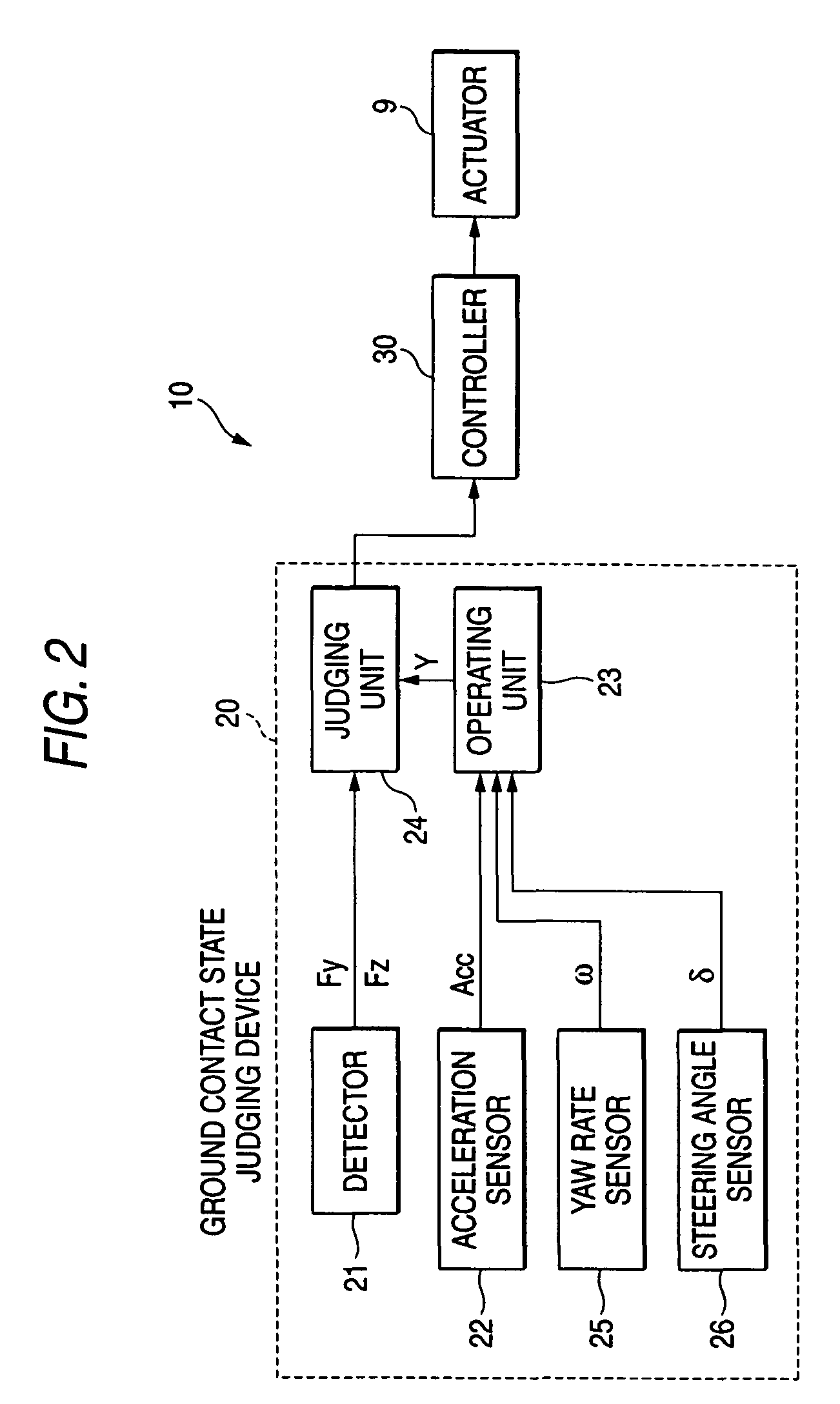
[0042]In the first embodiment, the contact-ground state is judged in terms of the whole of the wheels 5 at the front, rear, right and left sides, that is, the overall wheel. According to this embodiment, the whole of the wheels is divided into the front wheel side and the rear wheel side, and the ground-contact state is judged with respect to each of the front and rear wheel sides. The overall system construction and the basic portion concerning the control procedure are the same as the first embodiment, and thus the description thereof is omitted (the same is applied to an embodiment described later). The system construction of this embodiment is different from that of the first embodiment in that a yaw rate sensor 25 is further provided.

[0043]The yaw rate sensor 25 is a well-known sensor for detecting the yaw rate ω of the vehicle, and the detection signal of the yaw rate sensor 25 is output to the calculator 23. The calculator 23 calculates the total Yf_tot of the cornering force...

third embodiment

[0049]In the above embodiments, the ground-contact state is judged by comparing the lateral force Fy and the cornering force Y. However according to this embodiment, the ground-contact state as the overall wheels is judged on the basis of the vertical force Fz. That is, it is necessary to compare the vertical force Fz as a detection value with the actual vertical force T to judge the ground-contact state, however, it is difficult to detect the actual vertical force T. Therefore, when the judgment based on the vertical force is made, for example, the total of the vertical forces Fz of the respective wheels 5 when the vehicle is at a standstill is detected as a reference value Ttot in advance. Then, it is judged whether the total Ftot_z of the vertical forces detected at some timing is sufficiently smaller than the reference value Ttot, that is, smaller than the multiplication of the reference value Ttot and a predetermined constant K (05 is bad (Ftot_z5 and the rear wheels 5 as in th...


PUM


Abstract

In wheel ground-contact state judging device and method, a detector directly detects a lateral force acting in a direction perpendicular to the wheel center plane of a wheel. An acceleration sensor detects an acceleration in the lateral direction of a vehicle. A calculator calculates a cornering force acting on each wheel on the basis of the acceleration in the lateral direction thus detected. A judging unit compares the detected lateral force with the calculated cornering force to judge whether the ground-contact state of the wheel is good or not.

Description

CROSS REFERENCE TO RELATED APPLICATIONS[0001]The disclosure of Japanese Application No. 2004-204570 filed on Jul. 12, 2004 including the specification, drawings and abstract is incorporated herein by reference in its entirety.BACKGROUND OF THE INVENTION[0002]1. Field of the Invention[0003]The present invention relates to a device and a method for judging a wheel ground-contact state, and a vehicle motion control device.[0004]2. Description of the Related Art[0005]There is known a method of controlling a vehicle motion state in consideration of a ground contact state of wheel from the viewpoint of enhancing safety of a vehicle when the vehicle is turning. According to this control method, it is required to monitor the ground-contact state of the wheel, and thus the ground-contact state is estimated on the basis of a roll angle occurring in the vehicle or a roll angular velocity. This is because when rolling occurs in the vehicle, the wheels of the vehicle are inclined with respect to...

Claims


Application Information

Patent Timeline
Patent Type & Authority Patents(United States)
IPC IPC(8): G06F19/00G06G7/76G06G7/00G06F17/00B60K28/12B60D1/28B60K28/14B60K28/00B62D49/08B60R21/00B60L3/00B60G17/015B60G17/018B60G21/055B60W40/10B60W40/109
CPCB60G17/0162B60G21/0555B60G2400/104B60G2400/822B60G2600/02B60G2800/214B60G2800/24B60G2800/702B60G2800/9122
Inventor TSUKASAKI, YUICHIROKOGURE, MASARU
Owner SUBARU CORP
Why Eureka
Try Eureka