Package for felting needles

a needle and needle foot technology, applied in the field of needle foot packaging, can solve the problems of inability to damage the working parts of the needle foot by the needle foot, and achieve the effects of reducing the danger of needle foot injury, avoiding skin irritation, and improving handling

Active Publication Date: 2010-09-21
GROZ BECKERT KG
View PDF25 Cites 23 Cited by
  • Summary
  • Abstract
  • Description
  • Claims
  • Application Information

AI Technical Summary

Benefits of technology

[0007]The handling is improved. An operator may hold the wedge-shaped receptacle in one hand and grasp, with the other hand, the holding or foot portions of the felting needles and remove a desired quantity thereof from the receptacle. The operator does not come into contact with the working parts of the felting needles. The danger of injury by the barbs, forks or tips is thus significantly reduced.
[0008]Also, the needles are better protected than before in the needle package according to the invention. The needles lie side-by-side in the same orientation thus ensuring that their working parts will not be bent. The receptacle is preferably structured in such a manner that the felting needles are situated at the narrow side of the receptacle without abutting it. In principle, the receptacle may be open at the narrow side. It is preferred, however, that the narrow is of a closed construction for protecting the tips and working parts of the felting needles.
[0009]In a needle package thus structured, the operator may grasp the receptacle closed at the narrow side with one hand without coming into contact with either oil or anti-rust means or with the needles and their working parts; thus the operator is not directly exposed to anti-rust oil. In this manner skin irritations are reduced or avoided. The needle has to be grasped only at its foot region. Because in that region the needles regularly are significantly less oiled, the danger potential concerning skin irritations and allergies is minimized. Further, overall less anti-rust oil has to be used. The needles lie in the receptacle closely to one another. The danger of anti-rust oil dripping out resulting in the corrosion of individual needles is significantly reduced.
[0010]The cross section of the receptacle and the quantity of felting needles are coordinated to one another in such as manner that the felting needles lie closely packed in the receptacle without play. Preferably, particularly in the region of the receptacle opening, that is, in the region of their upper shank, they have no play, so that they are firmly wedged against one another in the receptacle. The receptacle preferably has a rectangular cross section; it may, however, be designed to have a different shape. The receptacle continuously increases from its narrow side toward its wide side, whereby it preferably has the shape of a truncated pyramid. The surface ratio of the narrow side to the wide side corresponds preferably to the cross-sectional surface ratio of the felting needles between the working part and the shank part. Such an arrangement likewise provides that the felting needles snugly fit, side-by-side, in the truncated pyramidal receptacle without any rattle. The dimensions of the receptacle and the quantity of the needles are coordinated with one another in such a manner that the needle tips are at a slight distance from the narrow end face of the receptacle. Such an arrangement prevents damages during transportation even in case of rough handling and delicate needle structures.

Problems solved by technology

In this manner damaging of the working parts of the needles by the needle feet is impossible.

Method used


Image

  • Package for felting needles
  • Package for felting needles
  • Package for felting needles

Examples


Embodiment Construction

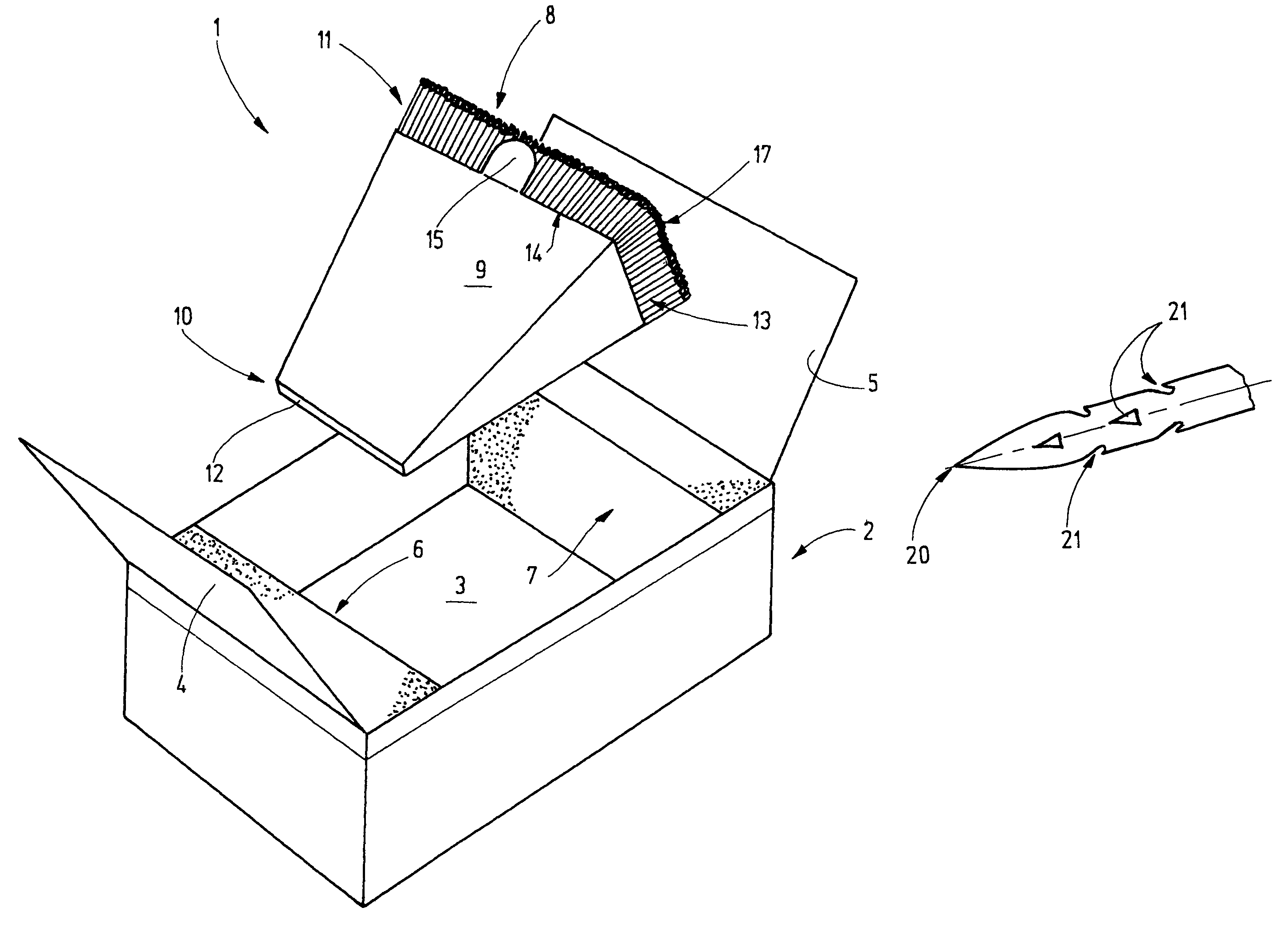
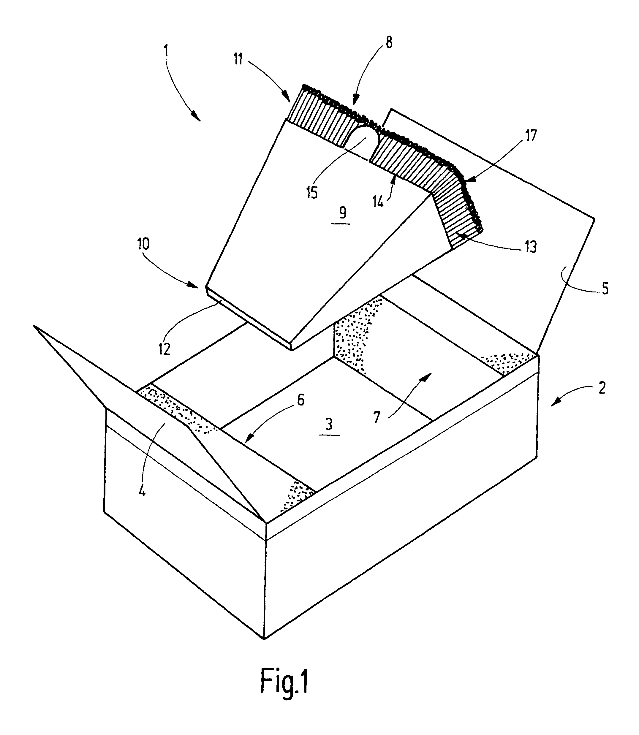
[0020]FIG. 1 shows a needle package 1 in an open state. The needle package 1 comprises a preferably plastic, for example, cuboid box 2 whose lid is removed in FIG. 1 and is therefore not shown. In the box 2 an oil paper 3 is placed, whose ends 4 and 5 project from the narrow sides of the box 2. The oil paper 3 preferably occupies the entire width of the inner space of the box 2. At the two end faces of the box 2 buffers 6, 7 are positioned which are cuboid blocks and which are preferably of foam rubber or another suitable material. Between the buffers 6, 7 a free space is provided for receiving a quantity of felting needles 8. In the present embodiment, for example, 250 felting needles are received together in a receptacle 9 which is preferably of a plastic material, such as PE. The receptacle 9 has the basic shape of a truncated pyramid and thus has in essence the shape of a wedge. Its four lateral faces are trapezoidal, and the oppositely-located lateral faces are congruent. In ac...


PUM

PropertyMeasurementUnit
lengthsaaaaaaaaaa
lengthaaaaaaaaaa
widthaaaaaaaaaa

Abstract

A wedge-shaped receptacle (9) is provided for packaging felting needles (8). The wedge shape is configured in such a manner that the felting needles lie in the receptacle in a mutual lateral engagement, that is, they are held approximately parallel to one another and they firmly clamp one another without their tips abutting against the receptacle body. This, on the one hand, results in a particular protection of the felting needles (8) during transportation and, on the other hand, results in a simple handling with the lowest danger of injuries.

Description

CROSS-REFERENCE TO RELATED APPLICATION[0001]This Application is a U.S. Utility Patent Application which claims priority from German Application No. 10 2005 036 329.6, filed Jul. 29, 2005, the complete disclosure of which is incorporated herein by reference.BACKGROUND OF THE INVENTION[0002]The invention relates to a needle package, particularly for felting needles and particularly for felting needles having a fineness from gauge 38 and finer, as well as for crown needles having a fineness of gauge 36 and finer. The needle package according to the invention is further adapted for fork needles, particularly those having a fineness of gauge 36 to 43.[0003]Felting needles have long been used in textile technology for fixing. In this process the needles periodically pierce through the non-woven, random-fiber material in rapid succession. This causes needle wear, so that from time to time the needles have to be replaced. Since for each needle change a relatively large quantity of felting n...

Claims


Application Information

Patent Timeline
Patent Type & Authority Patents(United States)
IPC IPC(8): B65D85/28D05B85/00B65D5/00B65D81/03
CPCB65D5/5028B65D77/0413B65D85/24B65D85/20
Inventor WIZEMANN, GUSTAVCONZELMANN, RENE
Owner GROZ BECKERT KG
Why Eureka
Try Eureka