
Diamond wire saw

a diamond wire saw and diamond technology, applied in the field of diamond wire saws, can solve the problems of disadvantaged wire saw, diamond wire saw is no more serviceable, wire saw is unsuitable for cutting along curved paths with small radii of curvature,

Inactive Publication Date: 2010-09-21
CHIANG HUEI CHEN
View PDF1 Cites 1 Cited by
  • Summary
  • Abstract
  • Description
  • Claims
  • Application Information

AI Technical Summary

Benefits of technology

"The present invention is a diamond wire saw with an improved structure that is manageable when operated along curved cutting paths with small radii of curvature. The wire saw has a diamond-studded metal-plated layer that is securely attached to a net-like structure made of metal wires and insulating wires. The metal-plated layer extends only up to two lateral sides of the insulating wires, making the wire saw flexible and durable. The wire saw has a low manufacturing cost, requires a minimum amount of material, and has a long service life. The technical effects of the invention include improved cutting effects, reduced manufacturing cost, and flexibility for curved cutting paths with small radii of curvature."

Problems solved by technology

In a diamond wire saw having the aforesaid structure; the metal-plated layer which wraps and secures the diamond particles to a surface of the wire saw is rigid and thus renders the wire saw unsuitable for cutting along curved paths with small radii of curvature.
In addition, the metal-plated layer tends to flake off so that the diamond wire saw is no more serviceable.
This type of wire saw is disadvantaged by its relatively large cord diameter, which leads to a kerf typically more than 11 mm in width.
In addition, this type of wire saw is also unmanageable when operated along curved cutting paths with small radii of curvature and incurs a considerable production cost.

Method used


Image

  • Diamond wire saw
  • Diamond wire saw
  • Diamond wire saw

Examples


Embodiment Construction

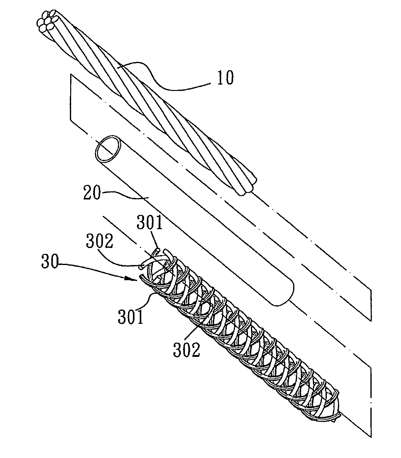
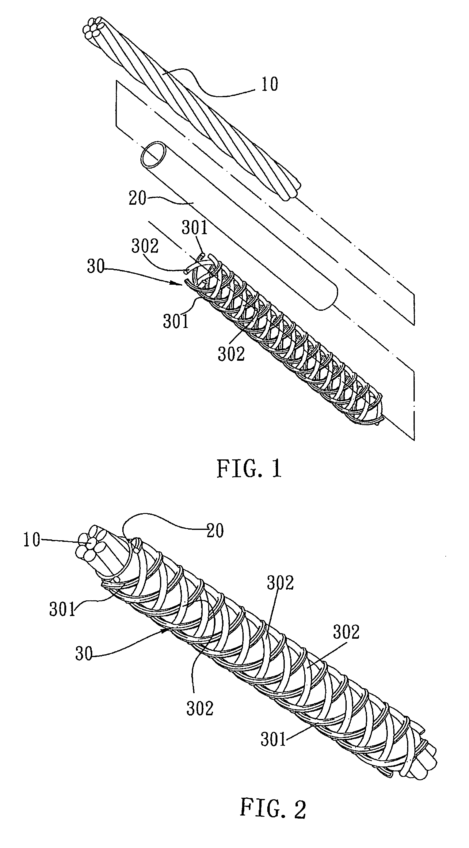
[0016]Please refer to FIG. 1 for an exploded perspective view of a diamond wire saw according to the present invention. As can be seen in the drawing, the diamond wire saw comprises a cord 10 having an outer surface covered by an insulating material 20 (also seen in FIG. 2). The insulating material 20 has an outer surface further covered by a net 30.

[0017]The insulating material 20 is closely attached to the outer surface of the cord 10 for providing an insulating effect and preventing chemicals used in a later electroplating process from permeating into the cord 10.

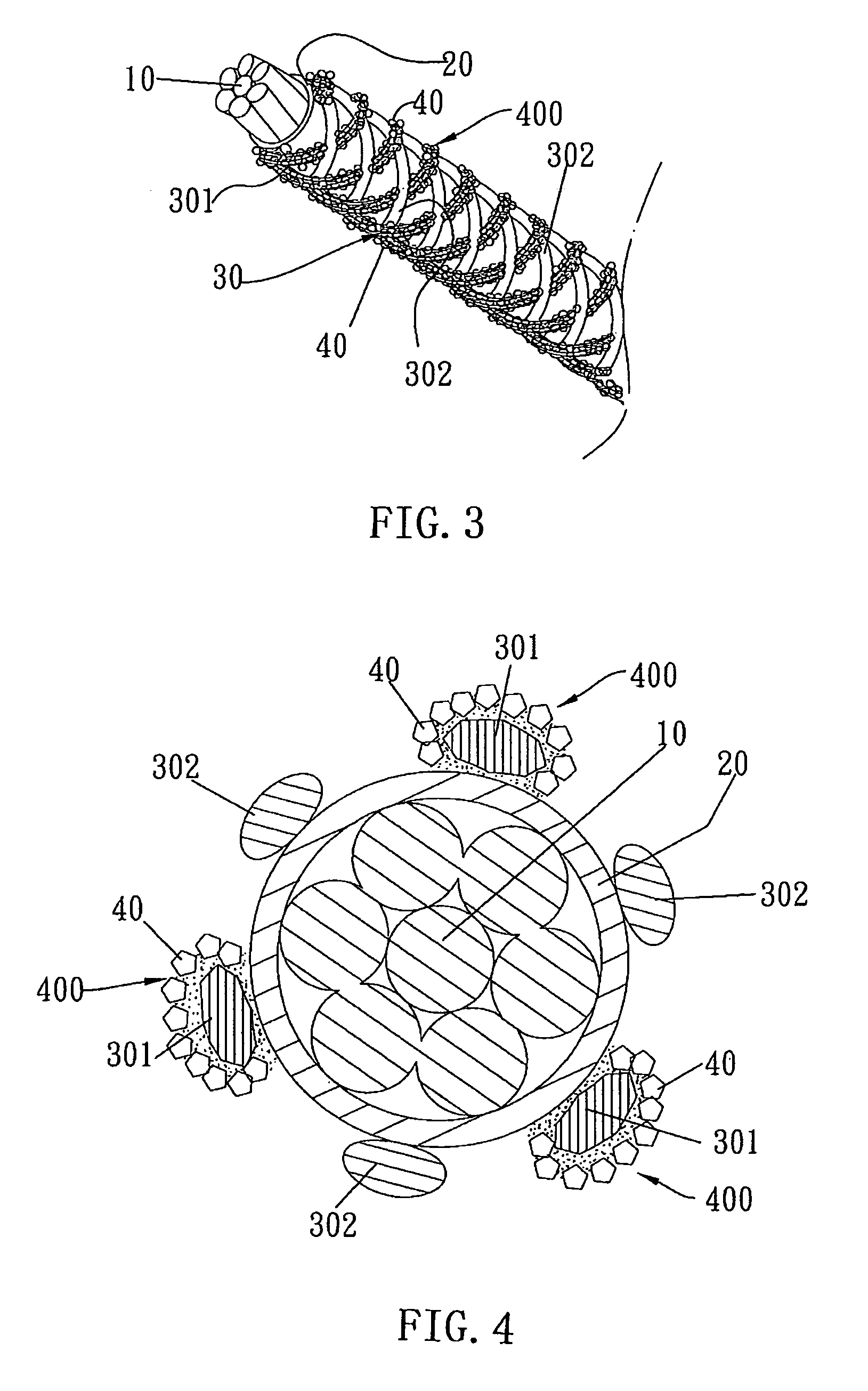
[0018]The net 30 is formed by metal wires 301 and insulating wires 302 which are interlaced into any possible net-shaped configurations. Therein, quantitative proportions of the metal wires 301 and of the insulating wires 302 used to form the net 30 are variable with practical needs.

[0019]Referring to FIG. 2, the cord 10 has its outer surface covered by the insulating material 20. Then, the outer surface of the insulatin...


PUM

PropertyMeasurementUnit
widthaaaaaaaaaa
diameteraaaaaaaaaa
diameteraaaaaaaaaa

Abstract

A diamond wire saw with an improved structure is provided. The diamond wire saw is capable of cutting operation along curved paths with small radii of curvature. In addition, the diamond wire saw is configured to prevent a diamond particle layer covering a surface thereof from flaking off. Thus, the diamond wire saw has improved durability and enhanced sharpness as well as low production cost.

Description

BACKGROUND OF THE INVENTION[0001]1. Technical Field[0002]The present invention relates to diamond wire saws and, more particularly, to a diamond wire saw with an improved structure capable of cutting various rigid or super rigid materials.[0003]2. Description of Related Art[0004]Known diamond wire saws mainly included the following two types.[0005]The first type uses a metal-plated layer to wrap and thereby secure diamond particles to a surface of a metal cable, so as to form a wire saw functioning as a tool for cutting rock, quartz, silicon crystal, and other highly rigid materials. In a diamond wire saw having the aforesaid structure; the metal-plated layer which wraps and secures the diamond particles to a surface of the wire saw is rigid and thus renders the wire saw unsuitable for cutting along curved paths with small radii of curvature. In addition, the metal-plated layer tends to flake off so that the diamond wire saw is no more serviceable.[0006]The second type refers to a w...

Claims


Application Information

Patent Timeline
Patent Type & Authority Patents(United States)
IPC IPC(8): B24B21/00B28D1/08
CPCB23D61/185
Inventor CHIANG, HUEI-CHEN
Owner CHIANG HUEI CHEN
Learn More