Negative pressure wound treatment apparatus and infection identification system and method

Inactive Publication Date: 2010-09-21
KCI LICENSING INC
View PDF146 Cites 35 Cited by
  • Summary
  • Abstract
  • Description
  • Claims
  • Application Information

AI Technical Summary

Benefits of technology

[0015]In accordance with the foregoing objects, the present invention generally comprises a foam pad for insertion substantially into a wound site and a wound drape for sealing enclosure of the foam pad at the wound site. The foam pad, comprised of a foam having relatively few open cells in contact with the areas upon which cell growth is to be encouraged so as to avoid unwanted adhesions, but having sufficiently numerous open cells so that drainage and V.A.C.® therapy may continue unimpaired, is placed in fluid communication with a vacuum source for promotion

Problems solved by technology

In many wounds however, this migration is slowed or non-existent due to the size of the wound, and the degree of infection.
One difficulty associated with the use of the V.A.C.® device, is that no suitable means for detecting the presence or kind of infection present in the wound is available, without disturbing the airtight dressing covering the wound.
Unfortunately, this process is hampered when a wound is large or has become infected.
Without sufficient blood flow, the epithelial and subcutaneous tissues surrounding the wound not only receive diminished oxygen and nutrients, but also are also less able to successfully fight bacterial infection and thus are less able to naturally close the wound.
Although still widely practiced and sometimes effective, such mechanical closure techniques suffer a major disadvantage in that they produce tension on the skin tissue adjacent the wound.
In particular, the tensile force required in order to achieve closure using sutures or staples may cause very high localized stresses at the suture or staple insertion point.
These stresses com

Method used


Image

  • Negative pressure wound treatment apparatus and infection identification system and method
  • Negative pressure wound treatment apparatus and infection identification system and method
  • Negative pressure wound treatment apparatus and infection identification system and method

Examples


Embodiment Construction

[0023]Although those of ordinary skill in the art will readily recognize many alternative embodiments, especially in light of the illustrations provided herein, this detailed description is exemplary of the preferred embodiment of the present invention, the scope of which is limited only by the claims that may be drawn hereto.

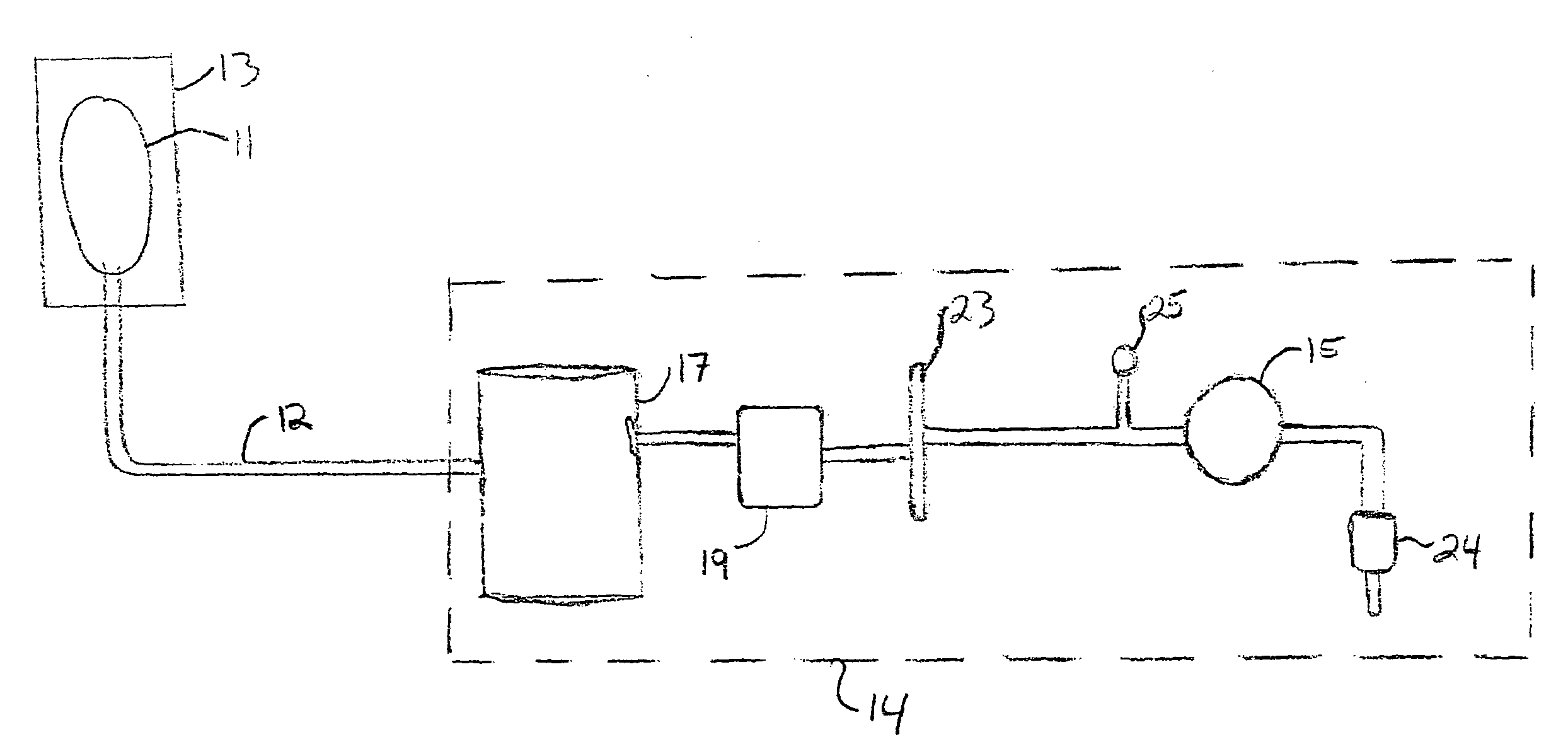
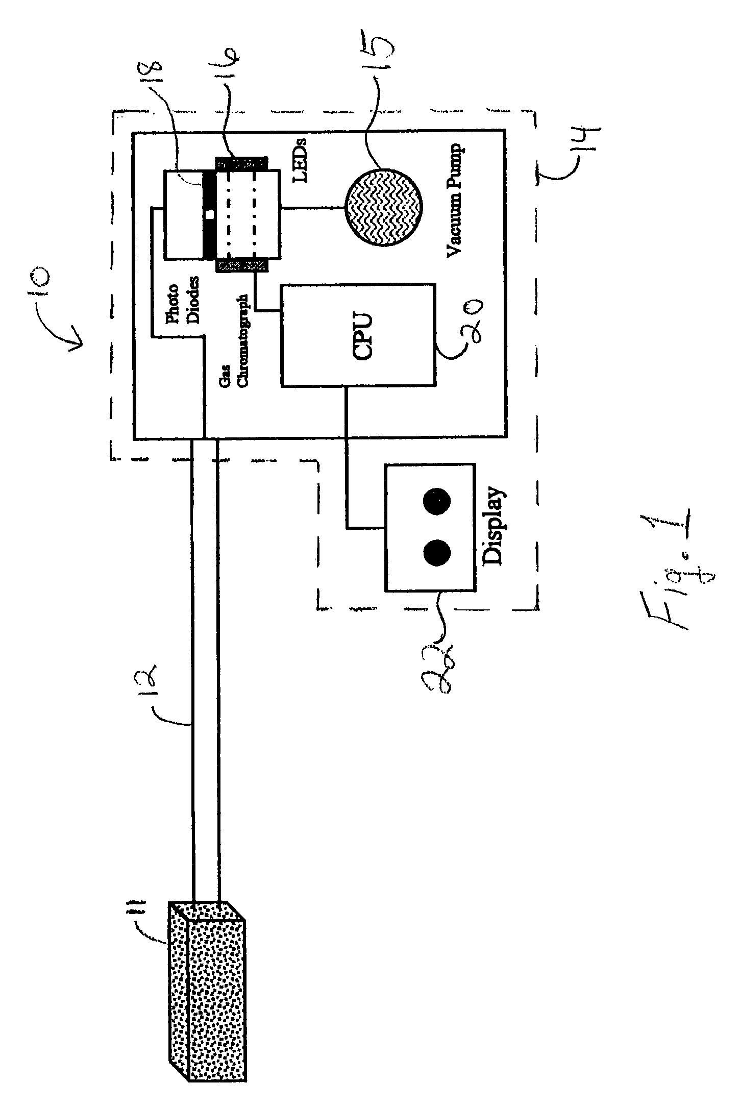
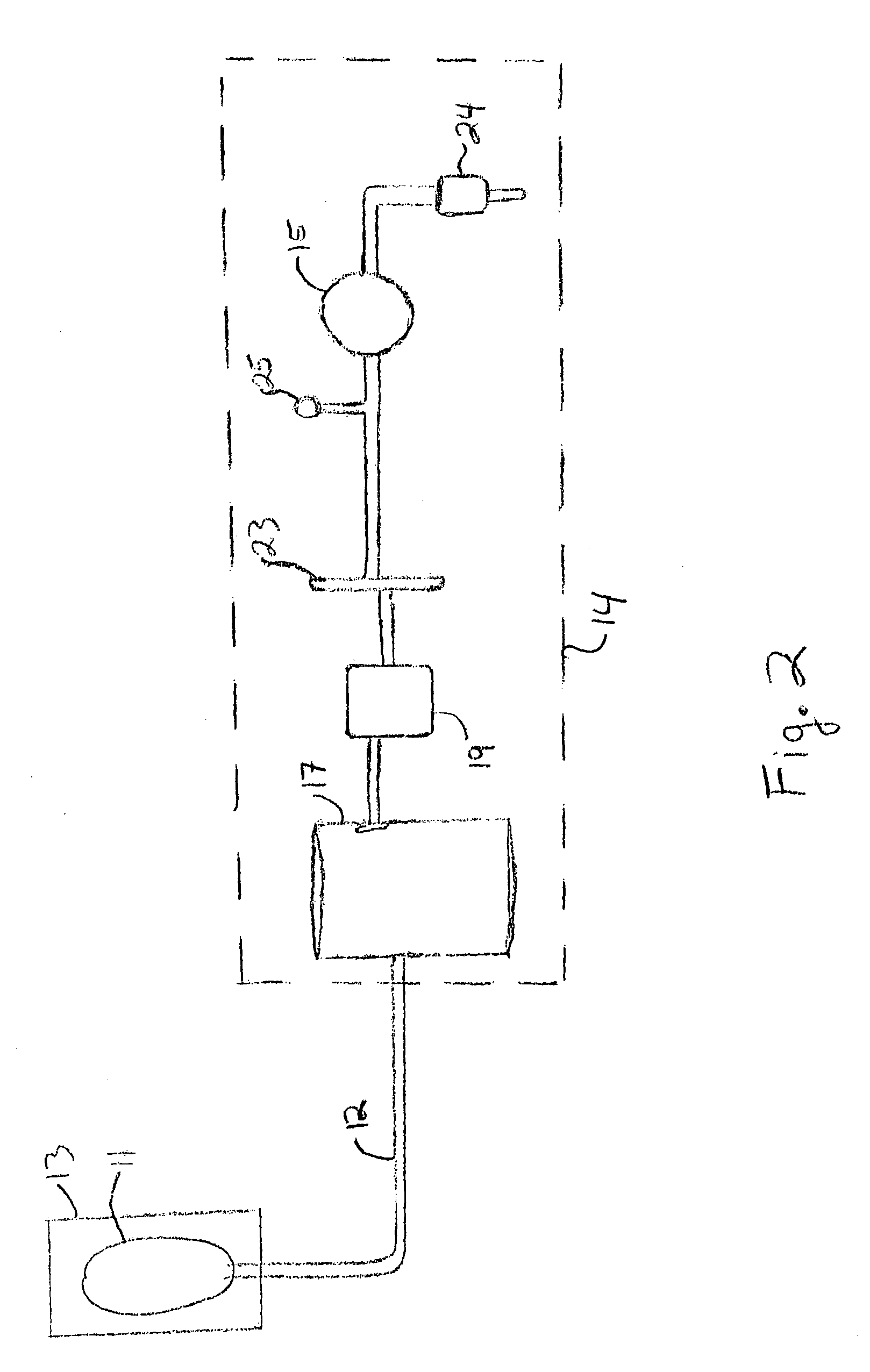
[0024]Referring now to the figures, and to FIG. 1 in particular, the present invention 10 is shown to generally comprise a foam pad 11, or other screen means, for insertion substantially into a wound site and a sealing means, such as a wound drape (not shown), for sealing enclosure of the foam pad 11 at the wound site. Flexible tubing 12 may be utilized to fluidically connect the foam pad 11 to a vacuum source 14. The vacuum source 14, which may encompasses a vacuum pump 15 and the sensing device, which may be comprised of a gas chromatograph 16. An exemplary gas chromatograph that may be utilized is disclosed in U.S. Pat. No. 5,611,846 issued to Overton, et al...


PUM


Abstract

A vacuum assisted wound closure device having a means for identifying infectious agents within a wound site. The vacuum assisted wound closure device includes a screen for placement within a wound site, a sealing means for covering the wound site, and a vacuum source in fluid communication with the screen. A canister may be disposed between the screen and vacuum source, such that fluids or other exudates that may be drawn from the wound during application of negative pressure by the vacuum source are collected in the canister for later disposal. A sensing device, which may be a gas chromatograph, sensor array, or other similar device capable of optically sensing the presence of a bacterial agent or other form of infection being drawn from the wound site, is disposed within the screen or interposed between the screen and the vacuum source.

Description

RELATED APPLICATIONS[0001]This application claims the benefit under 35 U.S.C. §119(e), of U.S. provisional patent application No. 60 / 273,587 filed Mar. 5, 2001.FIELD OF THE INVENTION[0002]The present invention relates to vacuum assisted wound treatment systems and methods, and more particularly to vacuum assisted wound treatment systems and methods that utilize a means for identifying infection through the use of optical analysis.BACKGROUND OF THE INVENTION[0003]Vacuum induced healing of open wounds has recently been popularized by Kinetic Concepts, Inc. of San Antonio, Tex., by its commercially available V.A.C.® product line. The vacuum induced healing process has been described in commonly assigned U.S. Pat. No. 4,969,880 issued on Nov. 13, 1990 to Zamierowski, as well as its continuations and continuations in part, U.S. Pat. No. 5,100,396, issued on Mar. 31, 1992, U.S. Pat. No. 5,261,893, issued Nov. 16, 1993, and U.S. Pat. No. 5,527,293, issued Jun. 18, 1996, the disclosures of ...

Claims


Application Information

Patent Timeline
IPC IPC(8): A61M1/00A61F15/00A61F13/00A61B5/00A61M27/00
CPCA61B5/445A61M1/0088A61M27/00A61B5/0059A61B5/14539A61M2205/3306A61M1/73A61M1/90A61M1/95
Inventor TUMEY, DAVID
Owner KCI LICENSING INC
Why Eureka
Try Eureka