Oscillating sensor and fluid sample analysis using an oscillating sensor

a technology of oscillating sensors and sensors, which is applied in the field of new sensor assembly and fluid sample testing method of the sensor, can solve the problems of friction between the sensor and the resonator, direct impact on the sensitivity of the resonator, damage to the fragile quartz plate, etc., and achieves the effect of effectively isolating the resonator, preventing any dampening of the vibration within the resonator, and enhancing the reproducibility of the vibration

Active Publication Date: 2010-09-28
BRUKER DALTONIK GMBH & CO KG
View PDF32 Cites 22 Cited by
  • Summary
  • Abstract
  • Description
  • Claims
  • Application Information

AI Technical Summary

Benefits of technology

[0012]According to one aspect of the present invention, a sensor is provided with a crystal resonator that is affixed to a substrate for the sensor with an adhesive that forms a rigid bond between the resonator and the substrate when cured. The rigid bond between the resonator and the substrate effectively causes the resonator to vibrate in a manner that is not affected by the connection of the resonator to the substrate. This rigid connection greatly enhances the reproducibility of the vibration that can be generated within the resonator by effectively isolating the resonator from the substrate. In other words, the rigid connection between the resonator and the substrate prevents any dampening of the vibrations within the resonator as a result of this connection, as opposed to prior art flexible connections between the substrate and resonator. Further, because the resonator is rigidly affixed to the substrate, during operation the resonator will not “creep” or shift position with regard to the substrate. As such, the resonator will remain in the same position throughout multiple uses of the sensor, such that the vibration characteristics of the resonator will not change, further adding to the reproducibility of the vibrations in the resonator.
[0013]According to another aspect of the present invention, the adhesive forming the rigid bond between the resonator and the substrate is present around the entire periphery of the resonator. This ensures that the vibration characteristics of the resonator are uniform across the entire resonator, to prevent any variations in these vibration characteristics of the resonator.
[0014]According to still another aspect of the invention, the resonator is mounted to a substrate of a sensor that enables the sample fluid to be injected into a stream of a control fluid already passing over the resonator. To offset the increased pressure exerted on the overall fluid stream passing over the resonator from the introduction of the sample fluid and avoid any inaccurate affects on the vibration of the resonator, the streams of the control fluid can be reduced in volume. This maintains the overall pressure of the fluid streams passing over the resonator at a constant level, such that the only effects on the vibration of the resonator are produced by the sample fluid.

Problems solved by technology

As noted by the patent's author, a problem of this resonator mounting configuration is that the O-rings or gaskets exert fluctuating and non-reproducible pressure on the oscillating resonator, which directly impacts the sensitivity of the resonator.
However, this setup has the following drawbacks: 1) sensor response is strongly influenced by mounting pressure of the sample fluid within the cell, and this pressure adjustment is not readily reproducible; 2) during assembly, the quartz plate is handled directly resulting in the risk of damaging the fragile quartz plate; and 3) even when fixed firmly between the O-rings, distortions due to pressure fluctuations in the tested liquid, and expansion or contractions of the plate due to thermal changes will stress the sensor plate and cause friction between the sensor and the O-ring which in turn will result in decreased Q-factor and unsteady oscillations, i.e. noise sensor response.
This description highlights one of the basic problems in the use of oscillating crystal resonators in liquid-based applications.
However, any and all physical contact with the resonator, i.e., from the sample fluid, the mounting structure, e.g., the O-rings, etc., dampens its oscillation freedom and thus lowers it sensitivity and overall functionality.
However, because the resonator oscillations propagate out to the edge of the piezoelectric plate (even if the coated electrode does not reach to the edge of the plate), any component making physical contact with the sensing surface will impact the resonator response.
Also, even slight distortions of the resonator from mechanical or thermal variations of the mounting assembly will result in noise added to the sensor response.
As a result, none of the designs disclosed in the applications facilitates the construction of a reproducible sensor assembly.
However, this improved design still suffers from a number of problems that have been discussed in literature publications released following the patent filing.
In particular, in practice it is very difficult to uniformly apply flexible adhesive around the edge of the very thin resonator plates (˜100 um) without depositing some amount of adhesive onto the sensing surface.
Thus, even slight imperfections on the mounting surface will result in irregular stress on the resonator and noise in the sensor response.
Another problem with the use of oscillating crystal resonators in liquid based applications is the signal noise and response reproducibility issues arising from changes in hydraulic pressure on the resonator surface(s) during sample analysis.
The processes involved with executing the additions and exchanges of sample and non-sample solutions to the sensing surface of the resonator result in pressure changes on the resonator surface(s), often resulting in non-reproducible stress on the resonators and dampening of the crystal oscillations.
These stresses and dampening events can greatly diminish the sensitivity and reproducibility of the resonators as mass measurement sensors.
A problem with this type of solution comes from the design constraints of applying pressure on the backside of the mounted resonator due to the presence of the electrodes and the detection electronics connected to those electrodes.
Also the intrinsic dampening of the resonator oscillations from exerting pressure on both faces of the resonator, and the difficulty in accurately matching the counter pressure on the driving electrode surface to the pressure being exerted on the sensing surface by the sample fluid or solution, make this practice highly impractical.
Thus, while the current resonator mounting designs are functional, they are far from optimal.
Often the influence from erroneous signals in the form of response dampening, random noise, and drift created by the resonator mounting process lowers the sensitivity and reproducibility of the resonator to such a degree that the technology is not feasible for the majority of desired applications as a liquid based sensor.

Method used


Image

  • Oscillating sensor and fluid sample analysis using an oscillating sensor
  • Oscillating sensor and fluid sample analysis using an oscillating sensor
  • Oscillating sensor and fluid sample analysis using an oscillating sensor

Examples


Embodiment Construction

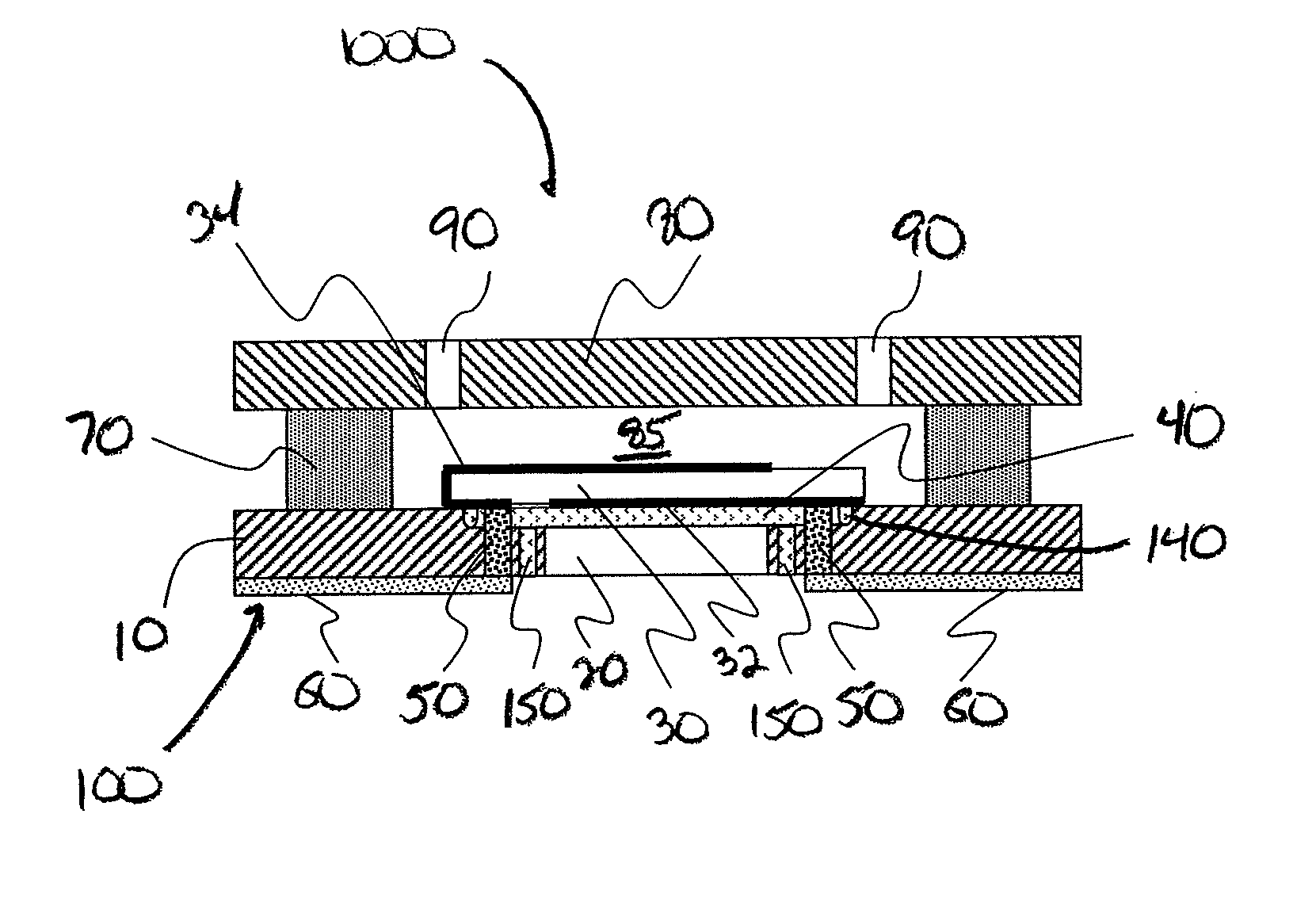
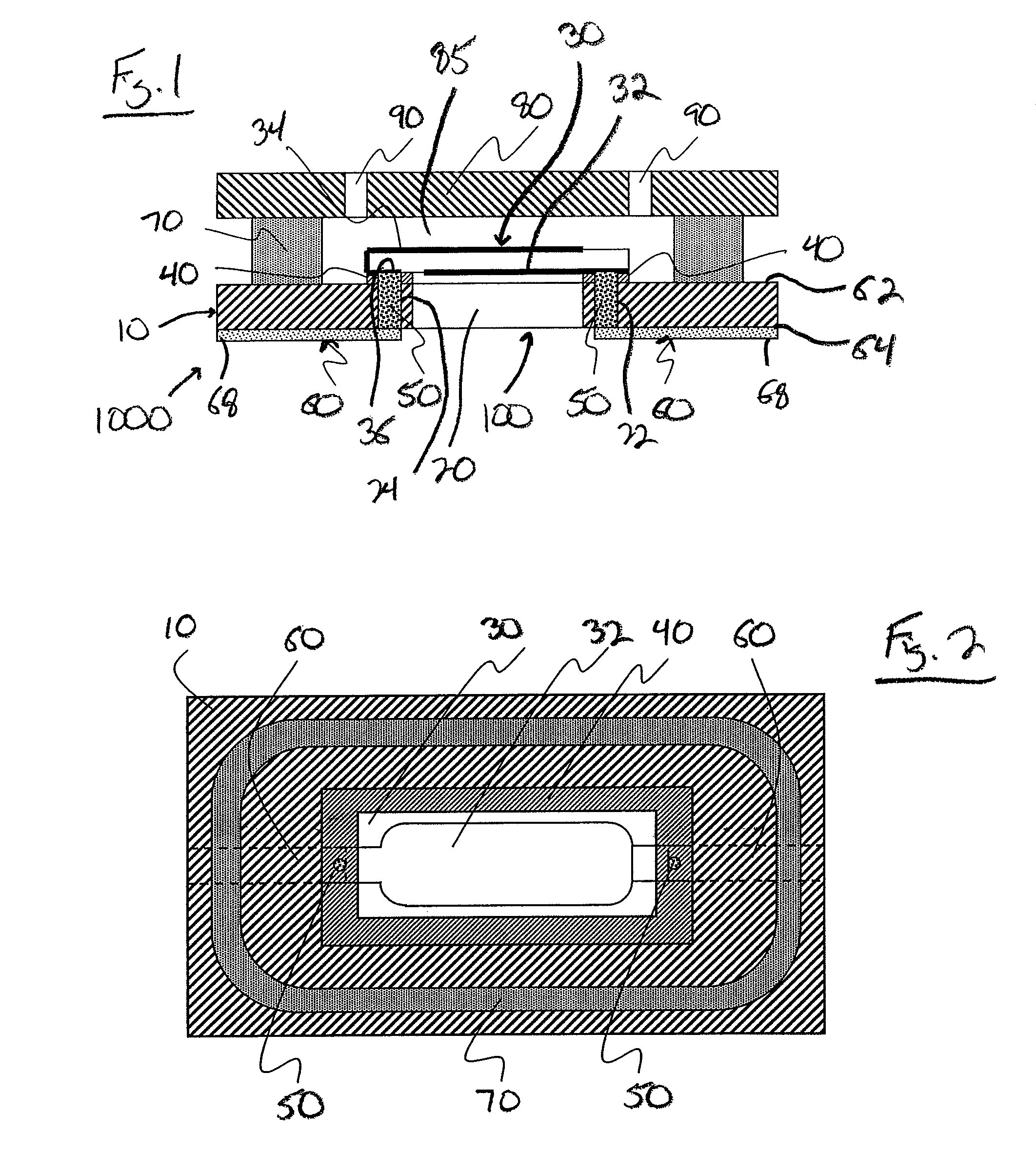
[0022]With reference now to the drawing figures in which like reference numerals represent like parts throughout the disclosure, a sensor assembly constructed according to the present invention is illustrated generally at 100 in FIG. 1. In one embodiment for the assembly shown in FIG. 1, the assembly 100 is a dry side sensor mounting assembly for a single sensing spot crystal resonator 30 assembled into a sample delivery flow cell 1000. The assembly 100 is formed with a substrate 10 of a fluid-impervious and non-conductive material that includes a central bore 20 and a pair of electrode contact bores 22, 24 disposed on opposite sides of the central bore 20, though the bores 22, 24 can be located in any suitable location around the bore 20. Additionally, the central bore 20 and the bores 22, 24 are shaped as desired to accommodate the particular structure of the assembly 100, and therefore can have any desired shape.

[0023]An oscillating crystal resonator 30 formed of a conventional q...


PUM

PropertyMeasurementUnit
adhesiveaaaaaaaaaa
conductoraaaaaaaaaa
hydrostatic pressureaaaaaaaaaa

Abstract

An assembly design for an oscillating resonator-based sensor where an oscillating crystal resonator such as a quartz crystal resonator is rigidly affixed or ‘mounted’ onto a solid substrate in such a fashion that the resonator can either rest flush against the substrate surface or upon a rigid mounting adhesive. Once cured, the mounting adhesive forms a liquid tight seal between the mounted resonator and the substrate such that only the sensing electrode surface will be exposed to fluids applied to the front side of the substrate. The mounted resonator assembly is designed in such a way that it can be interfaced with a fluid delivery system to form a liquid tight chamber or flow cell around the mounted resonator without incurring additional physical impact upon the mounted resonator. The assembled flow cell can in turn be used to direct multiple fluid streams to flow in a laminar manner over the sensing surface of the mounted resonator and by varying the rates of flow for the different laminar flowing fluid streams the total hydraulic pressure exerted on the surface of the mounted resonator can be held constant.

Description

FIELD OF THE INVENTION[0001]The invention regards a new sensor assembly and method of fluid delivery to the sensor, and more specifically pertains to a sensor assembly for fluid sample testing that includes a rigid attachment of the core sensing device to a mounting substrate to minimize and control all direct physical contact to the core sensing device of the assembly in conjunction with a unique method of test fluid delivery to control pressure fluctuations upon the core sensing device during operation.BACKGROUND OF INVENTION[0002]Oscillating crystal resonators can be used as very sensitive mass sensors in gas and liquid phase. It was shown by Sauerbrey (Sauerbrey, G., Z. Phys. 155 (1959), p. 206-222) that material deposited onto a resonator surface will change the resonators fundamental oscillation frequency proportional to the mass of the deposited material. Due to the extreme sensitivity of these resonators to changes in mass on their surfaces, oscillating crystal resonators ca...

Claims


Application Information

Patent Timeline
Patent Type & Authority Patents(United States)
IPC IPC(8): G01N29/27G01N29/032
CPCB01L3/502776G01N29/022G01N29/222B01L2200/146B01L2300/0627B01L2300/0877Y10T29/49002G01N2291/02466Y10T29/49826B01L2300/14
Inventor WHALEN, CHRISTOPHER D.WIEHLER, KLAUSKELLING, SVEN
Owner BRUKER DALTONIK GMBH & CO KG
Why Eureka
Try Eureka