Method of joining metallic and composite components

Inactive Publication Date: 2010-09-28
NASA
View PDF12 Cites 33 Cited by
  • Summary
  • Abstract
  • Description
  • Claims
  • Application Information

AI Technical Summary

Benefits of technology

[0009]In accordance with the invention, an improved method is provided for joining a metallic member or component to another member or structure made of a composite matrix ma

Problems solved by technology

However, no materials are perfect and the complexity of the underlying design requirements often lead to structures wherein multiple different materials are needed.
However, these methods suffe

Method used


Image

  • Method of joining metallic and composite components
  • Method of joining metallic and composite components
  • Method of joining metallic and composite components

Examples


Embodiment Construction

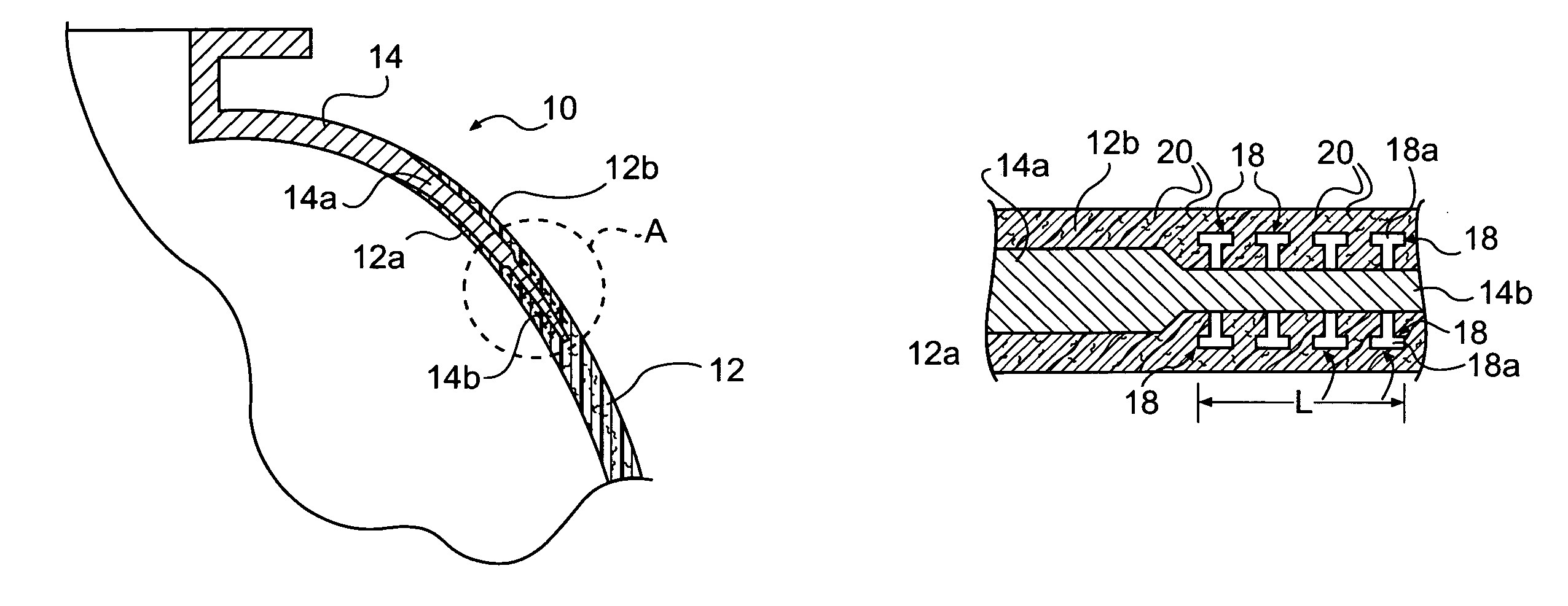
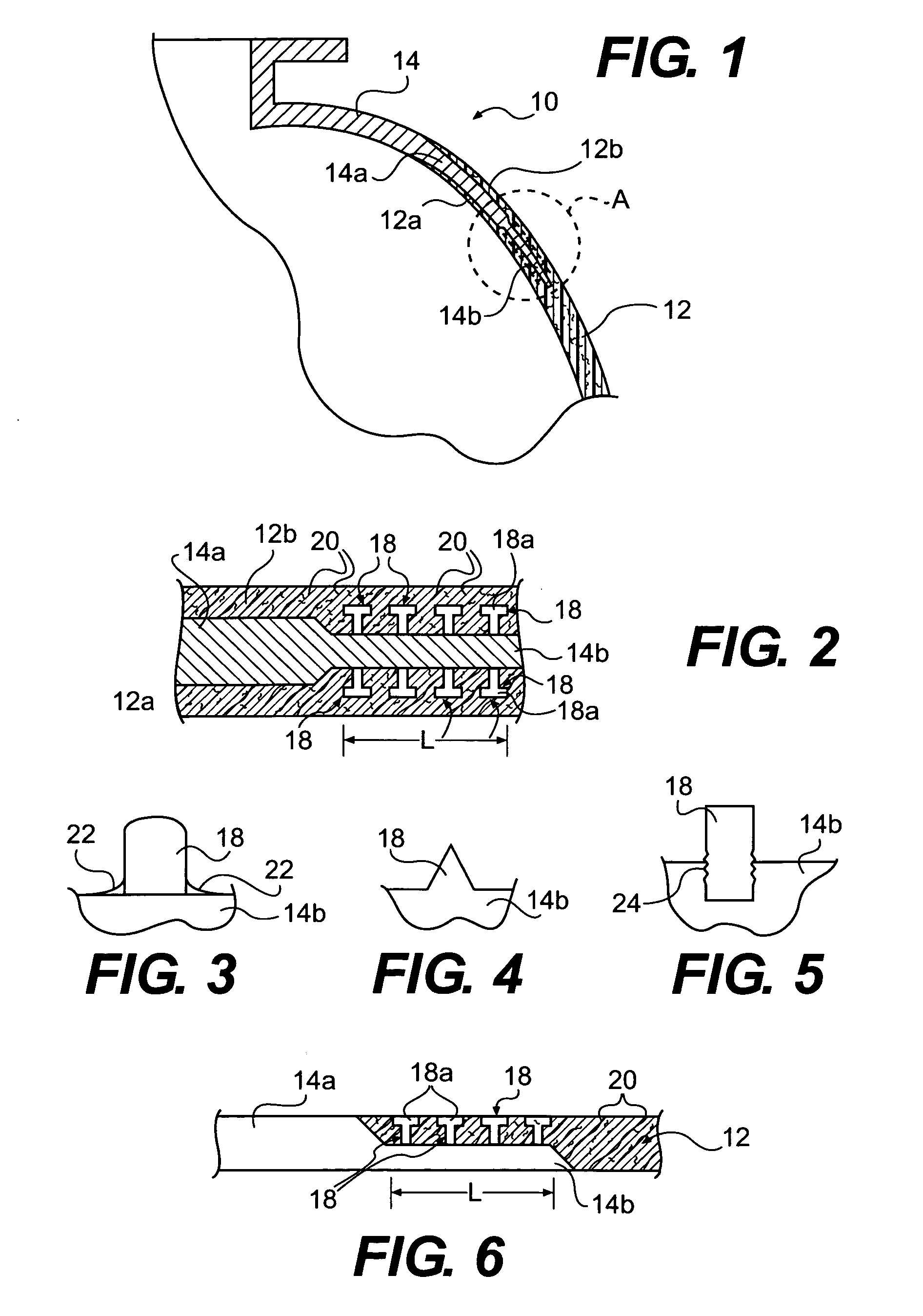
[0033]Referring to FIG. 1, there is shown a portion of tank or vessel 10 which includes a main, thin-walled body 12 that forms the basic thin-walled tank structure and defines the tank interior, denoted 10a, and a flange member 14 which is joined or affixed to tank body 12. Tank body 12, in this exemplary embodiment, is of a generally spherical shape, only a portion of which is shown. Tank body 12 is made of a composite matrix material and, more preferably, is made of either a ceramic composite matrix material or a polymeric composite matrix material. Flange member 14 is preferably made at least partially of metal and, more preferably, wholly of metal. As discussed above, tanks of this general type wherein a metallic flange or other mechanical attachment is affixed thereto are conventional, and the present invention concerns an improved method for joining a metallic member, in this case, flange 14, to a composite structure, in this case, tank or vessel 12.

[0034]In the exemplary embo...


PUM

PropertyMeasurementUnit
Structureaaaaaaaaaa
Metallic bondaaaaaaaaaa

Abstract

A method is provided for joining a metallic member to a structure made of a composite matrix material. One or more surfaces of a portion of the metallic member that is to be joined to the composite matrix structure is provided with a plurality of outwardly projecting studs. The surface including the studs is brought into engagement with a portion of an uncured composite matrix material so that fibers of the composite matrix material intertwine with the studs, and the metallic member and composite structure form an assembly. The assembly is then companion cured so as to join the metallic member to the composite matrix material structure.

Description

ORIGIN OF THE INVENTION[0001]This invention was made by an employee of the United States Government and may be manufactured and used by or for the Government for governmental purposes without the payment of any royalties.BACKGROUND OF THE INVENTION[0002]1. Field of the Invention[0003]The present invention relates to thin-walled composite structures such as polymeric matrix composite structures, and more particularly, to methods for joining mechanical attachments of various types to such structures.[0004]2. Description of the Related Art[0005]Composites are increasingly being used in a number of different applications. The relative light weight and high strength characteristics of ceramic matrix composites (CMCs) and polymeric matrix composites (PMCs) make such composites particularly attractive for use in, e.g., the aerospace industry wherein stringent weight and strength requirements are common. In this regard, both PMCs and CMCs have been used, where practical, in many aerospace a...

Claims


Application Information

Patent Timeline
IPC IPC(8): F16J15/00
CPCB29C66/5344B29C65/60B29C66/301B29C66/54B29C66/721B29C66/73111B29C66/742B29C66/83221B29C70/86B29C65/56B29C35/02B29C66/02242B29C66/303B29C66/30325B29C66/919B29C2793/0045B29C2793/0081B29K2105/06B29K2105/246B29K2305/00B29K2305/02B29L2031/3082B29L2031/3085B29L2031/3097B29L2031/712B29L2031/7156B29L2031/749B29L2031/7504B29C66/9141B29C65/00B29C65/02B29C66/12443B29C66/12463B29C66/30321B29C66/71B29C66/7212B29C66/72143B29C66/73751B29C66/7394B29C66/7461B29K2063/00B29K2307/04
Inventor SEMMES, EDMUND B.
Owner NASA
Why Eureka
Try Eureka