QR decomposition apparatus and method for MIMO system

a decomposition apparatus and mimo technology, applied in multiplex communication, orthogonal multiplex, wireless commuication services, etc., can solve the problems of inter-symbol interference, delay spread, and increase the complexity of equalizers, so as to simplify the hardware structure

Inactive Publication Date: 2010-09-28
ELECTRONICS & TELECOMM RES INST
View PDF9 Cites 2 Cited by
  • Summary
  • Abstract
  • Description
  • Claims
  • Application Information

AI Technical Summary

Benefits of technology

[0034]An embodiment of the present invention is directed to providing a QR decomposition apparatus and method for a Multiple Input Multiple Output (MIMO) system, which share multipliers, adders, and subtractors for simplifying a hardware structure.
[0035]Another embodiment of the present invention is directed to providing a QR decomposition apparatus and method for a MIMO system and a calculator for the QR decomposition apparatus, which reduce computation complexity and effectively use hardware by reducing the number of bits used in a multiplier using a floating point number processing method.

Problems solved by technology

In a wireless channel environment having multi-paths, delay spread occurs due to the multiple paths.
If delay spread time is longer than a symbol transmission interval, inter-symbol interference is caused.
However, complexity of the equalizer increases as a data transmission rate increases.
However, the described QR decomposition method may have a problem in that computation amount significantly increases for decomposing a channel H if the number of antennas constantly as seen in Eq.
That is, a hardware structure becomes complicated because the number of multipliers increases, and computation complexity also increases.

Method used


Image

  • QR decomposition apparatus and method for MIMO system
  • QR decomposition apparatus and method for MIMO system
  • QR decomposition apparatus and method for MIMO system

Examples


Embodiment Construction

[0057]The advantages, features and aspects of the invention will become apparent from the following description of the embodiments with reference to the accompanying drawings, which is set forth hereinafter.

[0058]FIG. 2 is a block diagram illustrating a QR decomposition apparatus in accordance with an embodiment of the present invention.

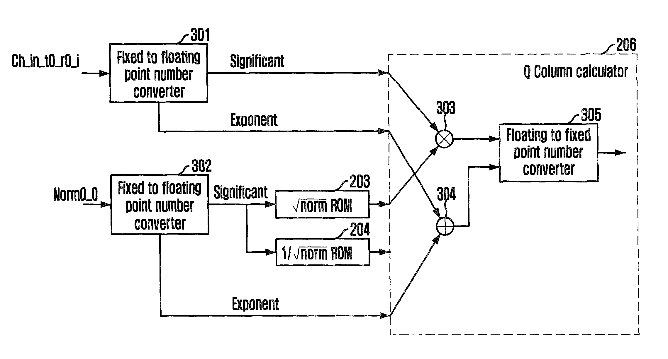
[0059]Referring to FIG. 2, the QR decomposition apparatus according to the present embodiment includes a norm calculator 201, a channel input delay 202, lookup table ROMs 203 and 204, a norm delay 205, a Q column calculator 206, a Q output memory 207, a Q column delay 208, an R row calculator 209, an R output memory 210, a Q update calculator 211, and a norm update calculator.

[0060]The norm calculator 201 receives channel input after Fast Fourier Transform (FFT) and calculates a vector size norm for qi through normi=∥qi∥2. The channel input delay 202 delays the channel input qi in order to use the channel input for calculating a column value of a uni...


PUM


Abstract

Provided are a QR decomposition apparatus and method for a MIMO system. The QR decomposition apparatus includes: a norm calculator for calculating a vector size norm for a channel input; a Q column calculator for calculating a column value of a unitary matrix Q by multiplying a delayed channel input with √{square root over (norm)}; an R row calculator for receiving the delayed channel input, the output of the Q column calculator, and 1 / √{square root over (norm)}, and calculating a row value of an upper triangular matrix R; a Q update calculator for receiving the delayed channel input, the output of the R row calculator, and a delayed output of the Q column calculator, and calculating a Q update matrix value; and a norm update calculator for receiving a delayed output of the norm calculator and an output of the R row calculator, and outputting a norm update matrix value.

Description

CROSS-REFERENCE TO RELATED APPLICATIONS[0001]The present invention claims priority of Korean Patent Application No. 10-2007-0131455, filed on Dec. 14, 2007, which is incorporated herein by reference.BACKGROUND OF THE INVENTION[0002]1. Field of the Invention[0003]The present invention relates to a QR decomposition apparatus and method for a Multiple Input Multiple Output (MIMO) system; and, more particularly, to an QR decomposition apparatus and method for improving performance with computation complexity reduced in an Orthogonal Frequency Division Multiplexing (OFDM) MIMO system.[0004]This work was supported by the IT R&D program of MIC / IITA [2006-S-002-02, “IMT-Advanced Radio Transmission Technology with Low Mobility”].[0005]2. Description of Related Art[0006]It is a requirement of a wireless communication system to transmit a large amount of high quality multimedia data using a limited frequency. As a method for transmitting a large amount of data using a limited frequency, a Mult...

Claims


Application Information

Patent Timeline
Patent Type & Authority Patents(United States)
IPC IPC(8): H04W4/00
CPCH04L25/0246H04L25/03006H04L2025/03414H04L2025/03426H04B7/0413H04L27/2647
Inventor LEE, YU-ROKIM, BYUNG-CHANCHEONG, MINHOYOON, CHANHOLEE, JE-HUNRYU, KWHANG-HYUNKIM, CHEOL-JUNGJEON, TAE-HYUNLEE, SOK-KYU
Owner ELECTRONICS & TELECOMM RES INST
Why Eureka
Try Eureka