Thrust fin for ships

a technology for thrust fins and ships, applied in special-purpose vessels, marine propulsion, vessel construction, etc., can solve the problems of difficult optimization of the angle between the thrust fin and the stream of fluid, energy loss, and angle of attack, so as to maximize the thrust of the ship, enhance the propulsive efficiency of the ship, and simple shape

Inactive Publication Date: 2010-10-05
HYUNDAI HEAVY IND CO LTD
View PDF9 Cites 0 Cited by
  • Summary
  • Abstract
  • Description
  • Claims
  • Application Information

AI Technical Summary

Benefits of technology

[0012]Accordingly, the present invention has been made keeping in mind the above problems occurring in the prior art, and the object of the present invention is to provide a thrust fin for a ship which has a simple shape, enhances propulsive efficiency of the ship, and can be applied to a real ship thanks to the simple installation thereof, to maximize thrust of the ship.

Problems solved by technology

The rotational flow is irrelevant to the generation of the thrust, but merely causes energy loss.
However, because this region has complex flow characteristics compared to other regions, it is very difficult to optimize an angle between the fin and a stream of fluid, that is, an angle of attack.
An axial acceleration factor of the fluid generates thrust, but an acceleration factor, related to a direction of rotation of the propeller, merely causes energy loss, without helping the thrust to increase.
However, most conventional additional devices are problematic in that they can improve propulsive efficiency only in a specific ship and under voyage conditions.

Method used


Image

  • Thrust fin for ships
  • Thrust fin for ships
  • Thrust fin for ships

Examples


example

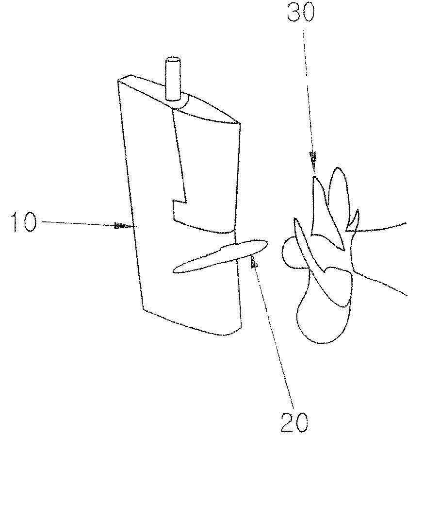
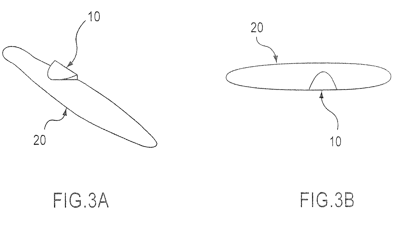
[0026]A thrust fin, which has a left length (compared to a propeller) of approximately 0.5 Rp and a right length of approximately 0.4 Rp (Rp: the radius of the propeller) and a maximum width (compared to the propeller) of 0.15 Rp, was attached to a rudder of a ship (see, FIGS. 5A and 5B), and a change in propulsive efficiency, according to the vertical position at which the fin is attached to the rudder, was tested.

[0027]As shown in FIG. 6, in the thrust fin developed through the study, it was confirmed that, when the thrust fin is attached to a position aligned with the central shaft, the propulsive efficiency is increased by approximately 6%, when it is attached to a position spaced apart from the central shaft in an upward direction by 0.15 Rp, the propulsive efficiency is increased by approximately 4%, and when it is attached to a position spaced apart from the central shaft in an upward direction by 0.3 Rp, the propulsive efficiency is increased by approximately 3%.

[0028]As des...


PUM


Abstract

Disclosed herein is a thrust fin for ships which recovers lost energy caused by rotational flow generated behind a propeller, and converts it into thrust. The thrust fin of the present invention has a simple shape, enhances propulsive efficiency of the ship, and can be applied to a real ship thanks to the simple installation thereof, to maximize thrust of the ship. The thrust fin is mounted to a front portion of the rudder of the ship such that left and right sides of the thrust fin, which are integrated with each other into a single body, are asymmetrical. A vertical position, at which the thrust fin is mounted to the rudder, is at an optimum position as determined in consideration of the shape of the rudder and hydrodynamic characteristics.

Description

CROSS-REFERENCE TO RELATED APPLICATION[0001]This application is a National Stage entry of International Application No. PCT / KR2005 / 004193, filed Dec. 8, 2005, the entire specification, claims and drawings of which are incorporated herewith by reference.BACKGROUND OF THE INVENTION[0002]1. Field of the Invention[0003]The present invention relates to a thrust fin for ships that recovers lost energy caused by rotational flow, which is generated behind a propeller, and converts it into thrust.[0004]2. Description of Related Art[0005]As well known to those in the art, a propeller of a ship generates thrust using its rotation, but rotational flow is generated behind the propeller while the propeller rotates, as shown in FIG. 1. The rotational flow is irrelevant to the generation of the thrust, but merely causes energy loss. Thrust fins are one type of device that enhances propulsive efficiency of the ship through the recovery of a large amount of energy loss caused due to the rotational fl...

Claims


Application Information

Patent Timeline
Patent Type & Authority Patents(United States)
IPC IPC(8): B63B1/24
CPCB63H5/16B63H25/38Y02T70/542Y02T70/545Y02T70/50E05D15/063E05D15/0665E06B3/4663E05F5/02E05Y2900/20E05Y2201/688E05Y2201/684
Inventor MIN, KEH-SIKCHANG, BONG-JUNLEE, HONG-GI
Owner HYUNDAI HEAVY IND CO LTD
Why Eureka
Try Eureka