Insulated spray cooling system for extreme environments

a technology of spray cooling system and spray cooling system, which is applied in the direction of electrical apparatus contruction details, operation mode of machine, lighting and heating apparatus, etc., to achieve the effect of increasing electronics performan

Active Publication Date: 2010-10-05
PARKER INTANGIBLES LLC
View PDF16 Cites 39 Cited by
  • Summary
  • Abstract
  • Description
  • Claims
  • Application Information

AI Technical Summary

Benefits of technology

[0018]Another object is to provide an insulated spray cooling system for extreme environments that provides increased electronics performance regardless of external environmental conditions.
[0019]A further object is to provide an insulated spray cooling system for extreme environments that isolates electronic devices from the external environment and external harmful elements.
[0020]A further object is to provide an insulated spray cooling system for extreme environments that has an insulated enclosure that significantly limits heat transfer from the coolant within the enclosure to the external environment.

Problems solved by technology

In addition, some external environments include hostile elements such as but not limited to dust, sand, debris, salt water, salt fog, condensed water vapor, contaminants and the like, which require the complete isolation of electronic components from the harsh external environment.

Method used


Image

  • Insulated spray cooling system for extreme environments
  • Insulated spray cooling system for extreme environments
  • Insulated spray cooling system for extreme environments

Examples


Embodiment Construction

A. Overview

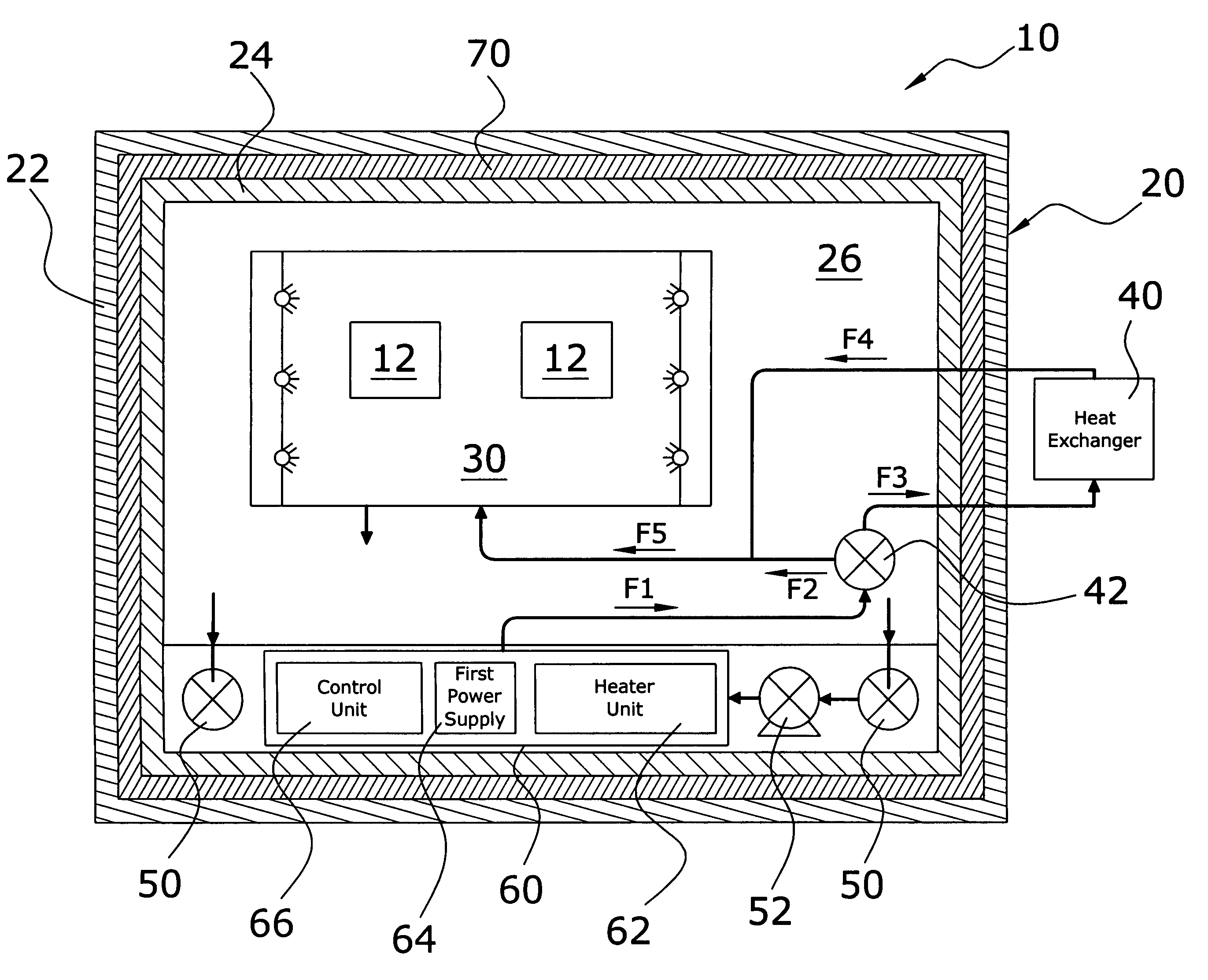
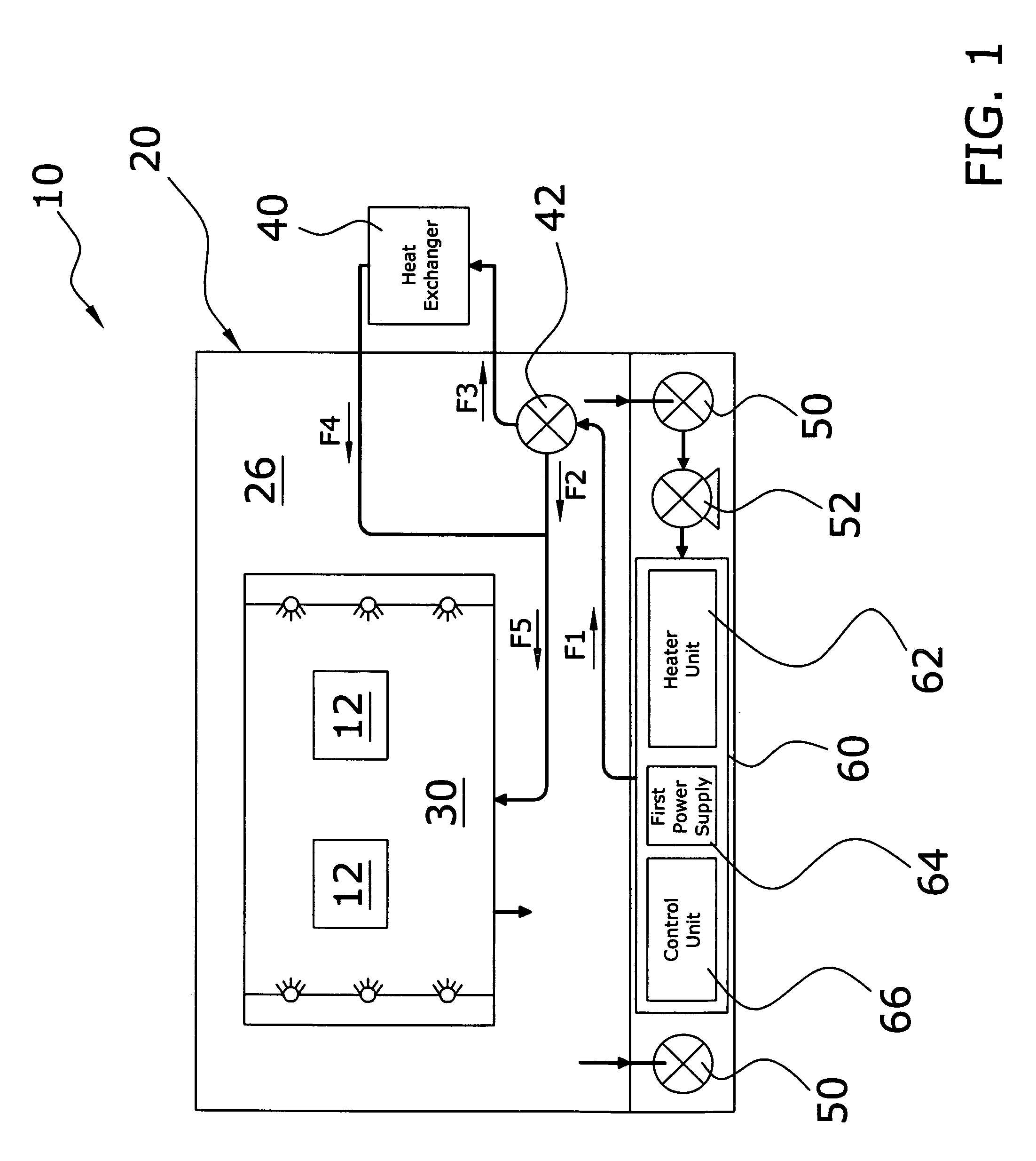
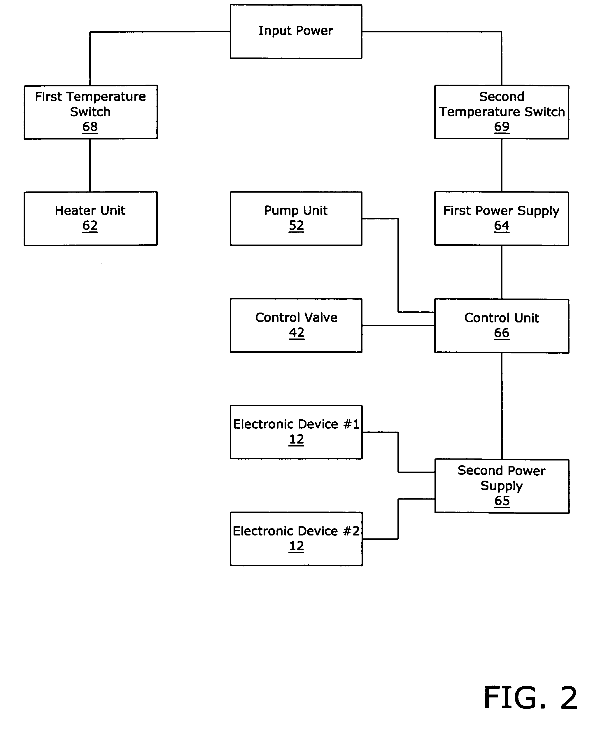
[0041]Turning now descriptively to the drawings, in which similar reference characters denote similar elements throughout the several views, FIGS. 1 through 15 illustrate an insulated spray cooling system for extreme environments 10, which comprises an enclosure 20 that isolates the electronic components from the external environment, a spray unit 30 within the enclosure 20 for thermally managing one or more electronic devices 12, a pump unit 52 fluidly connected to the spray unit 30, a heat exchanger unit 40 fluidly connected to the pump, and a control valve 42 fluidly connected between the heat exchanger unit 40 and the pump. An independent chamber 60 preferably houses a heater unit 62, a first power supply 64 and a control unit 66, whereby the heater unit 62 initially heats the coolant within the independent chamber 60 to a minimum operating temperature prior to operation of the electronic components. The present invention may be utilized in various extreme environment...


PUM


Abstract

An insulated spray cooling system for extreme environments for providing a desired enclosed environment for electronic devices regardless of external environmental conditions. The insulated spray cooling system for extreme environments includes an insulated enclosure that isolates the electronic devices being thermally managed from the external environment and a thermal management unit within the enclosure for thermally managing electronic devices.

Description

CROSS REFERENCE TO RELATED APPLICATIONS[0001]I hereby claim benefit under Title 35, United States Code, Section 120 of U.S. patent application Ser. No. 10 / 369,321 filed Feb. 18, 2003 and Ser. No. 11 / 255,456 filed Oct. 24, 2005. This application is a continuation-in-part of the application Ser. No. 10 / 369,321 and the application Ser. No. 11 / 255,456. The application Ser. No. 10 / 369,321 is now U.S. Pat. No. 6,976,528 with the issue fee paid on Oct. 27, 2005. The application Ser. No. 11 / 255,456 is a continuation from the Ser. No. 10 / 369,321 and is now U.S. Pat. No. 7,264,042. The application Ser. No. 10 / 369,321 and the application Ser. No. 11 / 255,456 are hereby incorporated by reference into this application.STATEMENT REGARDING FEDERALLY SPONSORED RESEARCH OR DEVELOPMENT[0002]The U.S. Government has a paid-up license in this invention and the right in limited circumstances to require the patent owner to license others on reasonable terms as provided for by the terms of Contract No. F336...

Claims


Application Information

Patent Timeline
Patent Type & Authority Patents(United States)
IPC IPC(8): H05K7/20
CPCH01L23/345H01L23/4735H01L2924/0002H01L2924/00
Inventor TILTON, CHARLES L.BEASLEY, WILLIAM J.MILLER, DOUGLAS W.PALMER, RANDALL T.
Owner PARKER INTANGIBLES LLC
Why Eureka
Try Eureka