Method and apparatus for damping vibrations in a motion simulation platform

a technology of motion simulator and damping device, which is applied in the field of moving platform, can solve the problems of high maintenance requirement, unrealistic representation of the performance and feel of the true airplane or helicopter, and the need for expensive and noisy accessory equipment such as pumps, and achieve the effect of limiting unwanted vibrations

Active Publication Date: 2010-10-05
CAE INC
View PDF20 Cites 22 Cited by
  • Summary
  • Abstract
  • Description
  • Claims
  • Application Information

AI Technical Summary

Problems solved by technology

In flight simulators, unwanted vibrations felt by the pilot can result in un-realistic representations of the performance and feel of the true airplane or helicopter.
However, hydraulic actuators present several disadvantages, among which are a high maintenance requirement, the need for costly and noisy accessory equipment such as pumps, hosing and the like, the risk of contamination or leakage of the hydraulic fluid, and a low energy efficiency.
However, electromechanical linear actuators have proved to date unable to cost-effectively reproduce the performance of their hydraulic counterparts, as many electromechanical linear actuators produce more undesirable vibrations, which are ultimately transferred to the motion platform and therefore the user therein, causing an elevated audible noise level in the motion cabin and a reduced life of the actuated equipment as a result of the additional vibrations.
Such damping systems are generally complex, costly and include a high number of parts which further augments the risk of equipment failure.
Other simpler vibration dampers for use with actuators are known, but are impractical for many applications including flight simulators because such dampers generally reduce all vibrations, including the desirable “cues” which the flight simulator must reproduce in order to adequately simulate an aircraft environment.

Method used


Image

  • Method and apparatus for damping vibrations in a motion simulation platform
  • Method and apparatus for damping vibrations in a motion simulation platform
  • Method and apparatus for damping vibrations in a motion simulation platform

Examples


Embodiment Construction

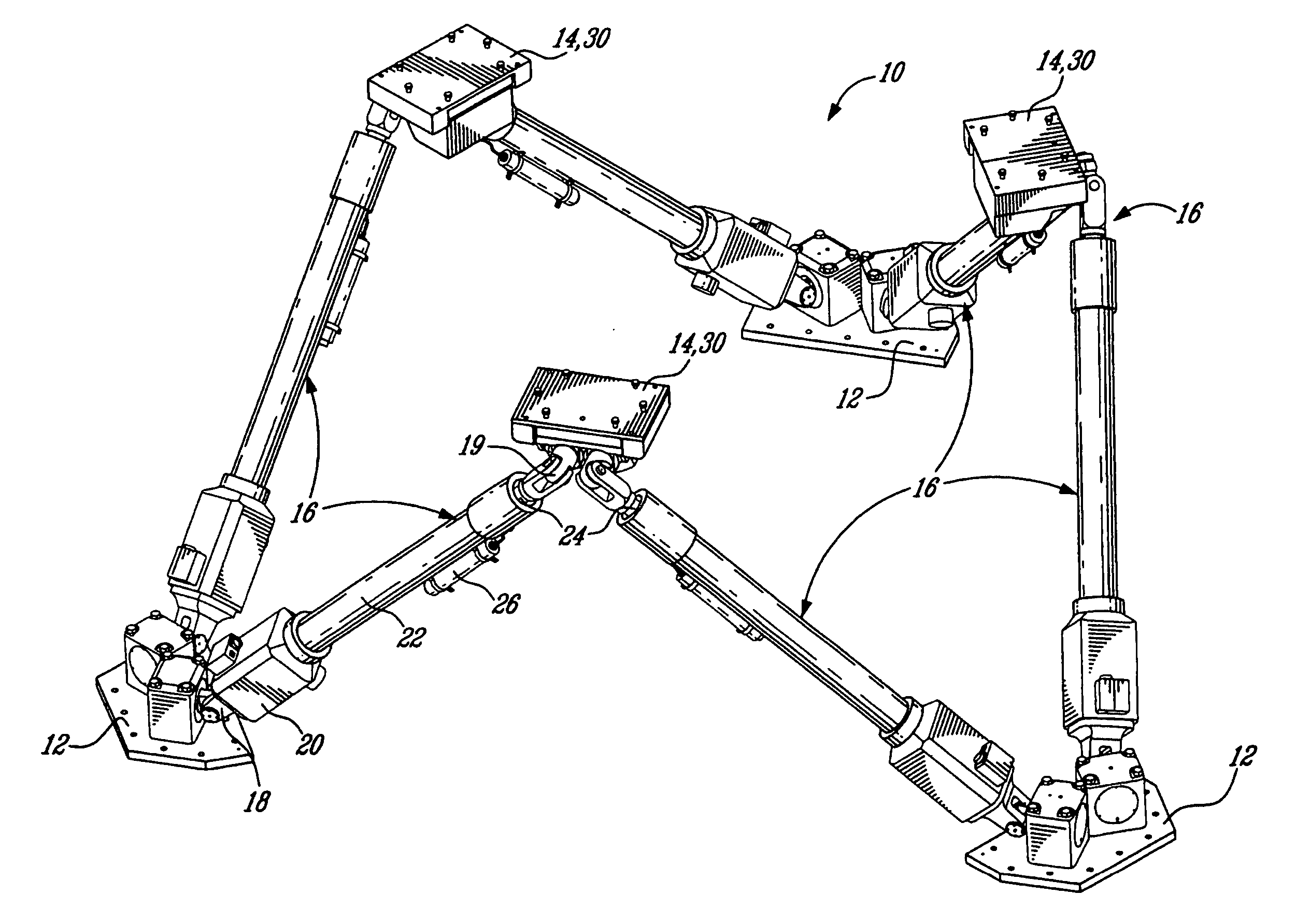
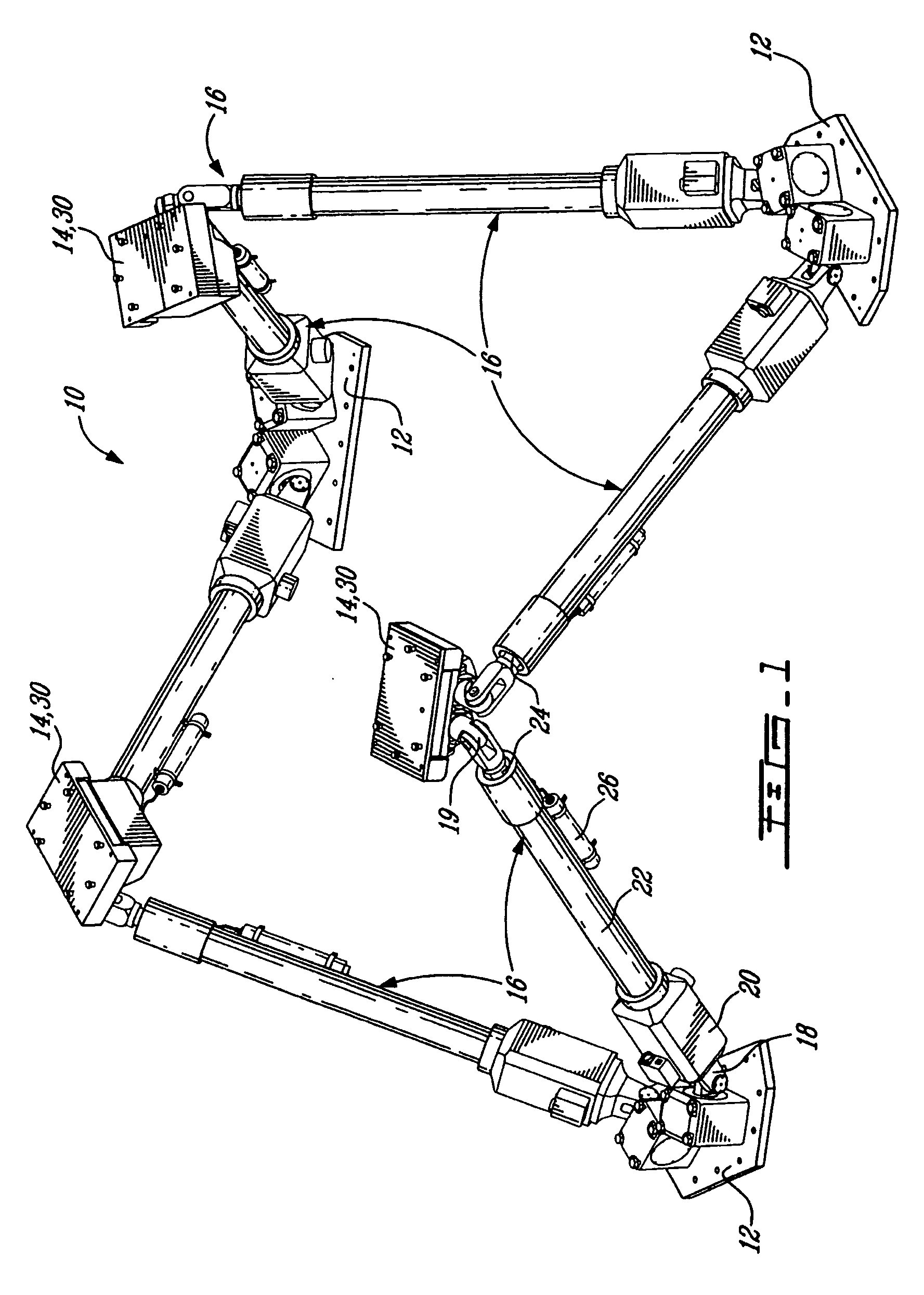
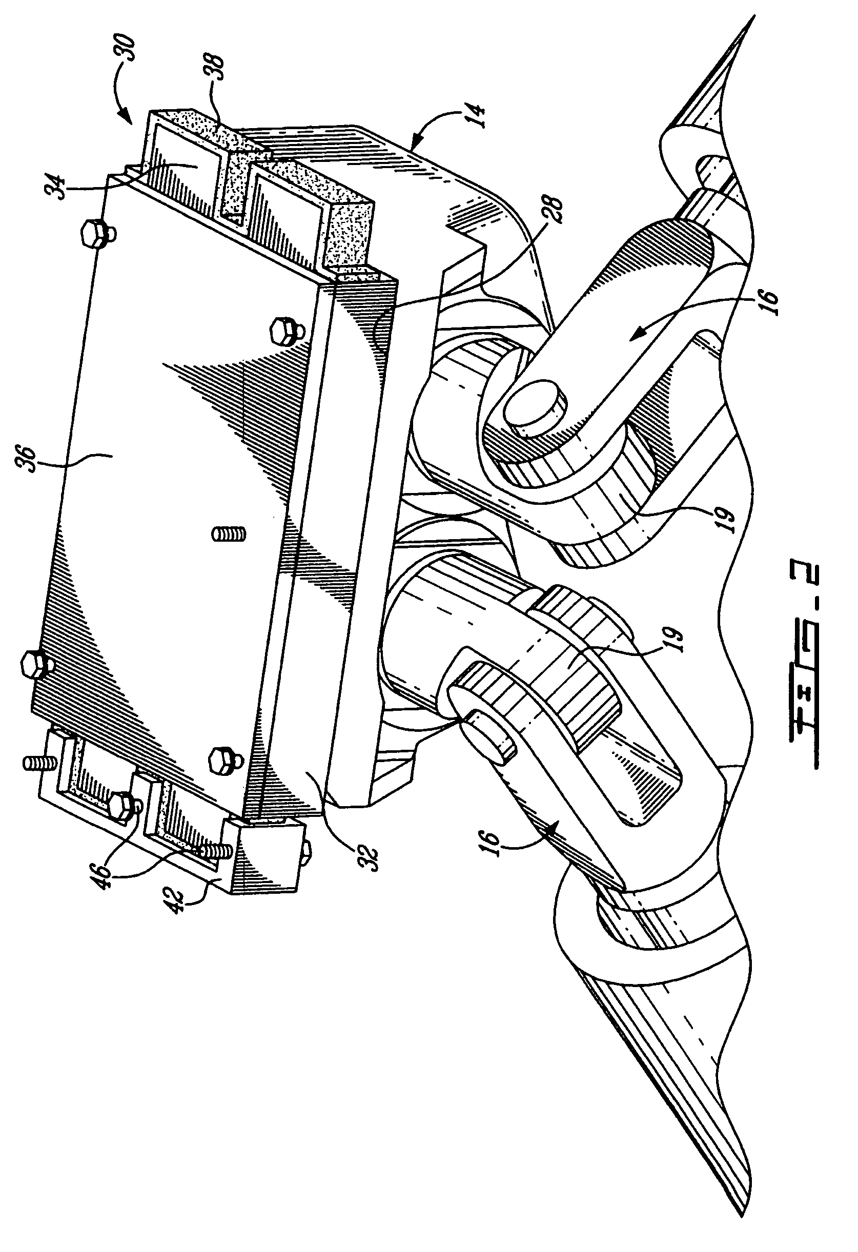
[0019]Referring now to FIG. 1, a motion system 10 for a displaceable motion platform, such as that of a motion simulator, of the type commonly known as a Stewart platform is shown. The platform assembly 10 includes a base formed of three base plates portions 12 fixed to an underlying support surface and therefore fixed relative to one another, six mobile and extensible legs or actuators 16 which have lower ends thereof engaged to the base plate portions 12 and opposed upper ends engaged to at least three bearing block assemblies 14 which support the moving platform of the motion simulator cabin. Such a motion system 10 is used to displace a motion simulator 50, such as that depicted in FIG. 5, which generally includes a simulator cabin 51 mounted on a displaceable motion platform 52. The motion platform 52 is displaced and controlled by linear actuators 16 such as those of the motion system 10. In the embodiment of FIG. 5, the vibration damping units 30 of the present invention, whi...


PUM


Abstract

A multiple degree-of-freedom motion simulator assembly comprises a fixed base, a displaceable simulator platform, and a plurality of linear actuators having upper ends thereof interconnected with the platform and lower ends thereof interconnected with the fixed base. A vibration damping unit is disposed between at least one of each of the upper ends and the platform and each of the lower ends and the fixed base. The damping units include at least a first resilient member preloaded and mounted to a major surface of a plate of the damping unit engaged to one of the ends of the linear actuator. The first resilient member provides vibration absorption such as to damp vibrations transmitted from the plate to the platform or base in at least a direction substantially perpendicular to the major surface.

Description

TECHNICAL FIELD[0001]The present invention relates to moveable platforms, particularly platforms of motion simulators, and more particularly to the damping of vibrations in such platforms.BACKGROUND OF THE ART[0002]Motion simulators are used for a variety of purposes, including entertainment and flight simulation for example, and usually comprise an upper platform which is mounted for movement relative to a fixed lower base and is operatively connected thereto by a plurality of actuators which move the platform as required in a desired number of degrees of freedom. Generally, undesirable vibrations are required to be limited as much as possible in order to minimize audible noise and wear of the simulator parts. In flight simulators, unwanted vibrations felt by the pilot can result in un-realistic representations of the performance and feel of the true airplane or helicopter. However, such a flight simulator must nonetheless reproduce certain vibrations which are true to those experi...

Claims


Application Information

Patent Timeline
Patent Type & Authority Patents(United States)
IPC IPC(8): G09B9/02
CPCG09B9/00G09B9/02G09B9/12
Inventor MALLACI, GIUSEPPEODDO, REMY
Owner CAE INC
Why Eureka
Try Eureka