Vacuum pump

a vacuum pump and vacuum technology, applied in the direction of machines/engines, liquid fuel engines, positive displacement liquid engines, etc., can solve the problems of difficult sense, accurate and good precision, and achieve the effect of reducing influence, good precision and good precision

Active Publication Date: 2011-05-05
EDWARDS JAPAN
View PDF7 Cites 27 Cited by
  • Summary
  • Abstract
  • Description
  • Claims
  • Application Information

AI Technical Summary

Benefits of technology

[0030]The present invention allows detecting, with good precision, physical contact between a rotor portion and a stator portion through detecting the occurrence of contact between the rotor portion and the stator portion when a specific vibration caused by contact between the rotor portion and the stator portion exceeds a predetermined threshold value.
[0031]Further, the present invention allows reducing the influence, exerted on the contact detection means, of resonance generated upon acceleration or deceleration of the rotor portio

Problems solved by technology

H6-101655 and 2004-117091, it was difficult to sense, accurately and with good precision, the occurrence whereby the amount of s

Method used


Image

  • Vacuum pump
  • Vacuum pump
  • Vacuum pump

Examples


embodiment 1

, Variation 4

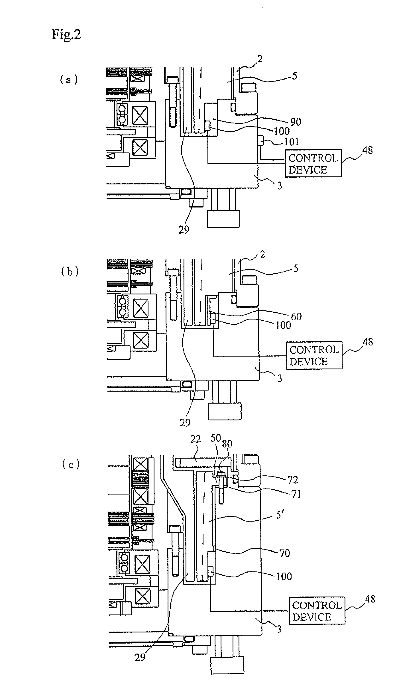
[0169]In Embodiment 1 and Variations 1 to 3 thereof, an instance where the vibration sensor 100 is disposed on the stator portion side has been explained as a method for detecting contact between the rotor portion and the stator portion inside the turbo-molecular pump 1. However, the method for detecting the particular vibration that occurs during contact between the rotor portion and the stator portion is not limited to the above-described one.

[0170]For instance, the occurrence or not of contact between the rotor portion and the stator portion may also be detected by detecting the vibration of the rotor portion, i.e. the change over time of the displacement of the rotor portion.

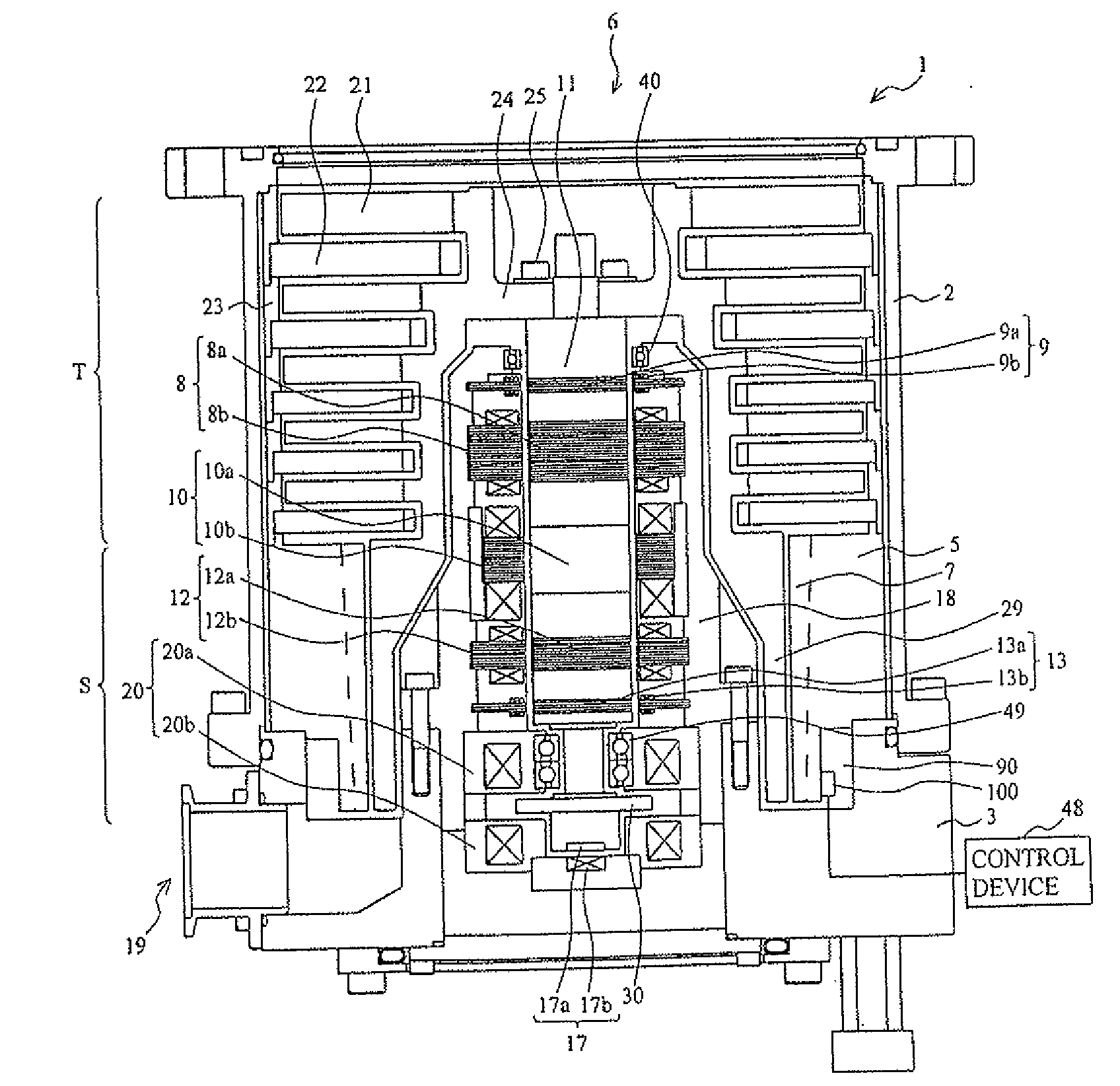
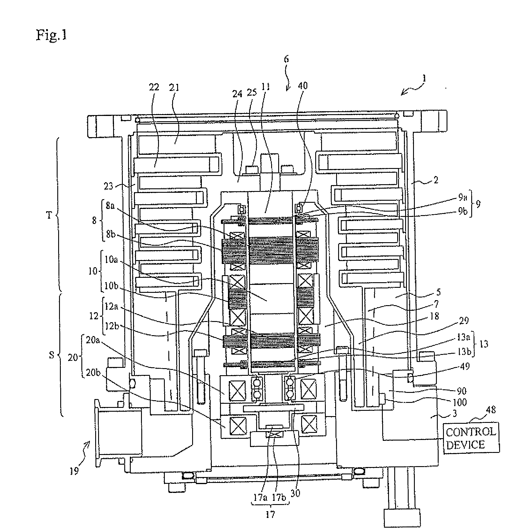
[0171]Specifically, there is provided a sensor that monitors the displacement of the rotor portion (rotary body), for instance, the shaft 11, the rotor section 24 (rotor blades 21, tubular member 29), such that the occurrence or not of contact between the rotor portion and the stator portion is ...

embodiment 2 variation 1

[0193]As illustrated in FIG. 6A, for instance, a ring groove 201 for fitting and fixing an O-ring 200 may be formed along the circumferential direction of the end face of the base 3, on the inlet port 6 side, and not in the thread groove spacer 5.

[0194]The ring grooves 110 (FIG. 4), 201 (FIG. 6) for fitting and fixing the O-ring 200 may be provided on both the thread groove spacer 5 and the end face of the base 3 on the side of the inlet port 6. In this case as well, the O-ring 200 that is used has a shape such that the cross-sectional diameter thereof is large enough to prevent contact between the thread groove spacer 5 and the base 3 during fixing of the thread groove spacer 5 to the base 3.

embodiment 2

, Variation 2

[0195]As illustrated in FIG. 6B, for instance, an annular flat plate-like elastic body 202 having vibration damping characteristics may be disposed, instead of the O-ring 200, between the thread groove spacer 5 and the end face of the base 3 on the side of the inlet port 6.

[0196]Specifically, the thread groove spacer 5 may be fixed in such a manner that the annular flat plate-like elastic body 202, formed at a position at which the bolt holes 203 for insertion of bolts 300 and the bushes 301 correspond to the four circumferentially equidistant bolt holes 108, is sandwiched between the end face of the base 3 on the side of the inlet port 6, and the face of the mounting section 107 on the side of the outlet port 19.

[0197]The explanation of Embodiment 2 and variations thereof described above deals with an instance in which the thread groove spacer 5 is fixed through four bolts 300. However, the number of fixing sites for the bolts 300 is not limited thereto, and need only ...


PUM


Abstract

Provided is a vacuum pump which can detect precisely physical contact between a rotor portion and a stator portion, and contact between the rotor portion and the stator portion that occurs as the amount of deposited solid product reaches the clearance between the rotor portion and the stator portion.
A vibration sensor is provided, taking advantage of a clearance, at the outer peripheral of a thread groove spacer. Contact between the rotor portion and the stator portion is decided, when a particular vibration during contact between the rotor portion and the stator portion exceeds a predetermined threshold value. The vibration sensor is mounted on the outer peripheral of the thread groove spacer at the end of the side of an exhaust port. The thread groove spacer is fixed on a casing via an elastic member (an O-ring) that have a vibration absorption (vibration damping) function of a cutoff frequency (fc1). A vibration signal outputted from the vibration sensor is converted into a digital vibration signal, and is inputted to a digital filter having a passing band of fc1 to fc2 [Hz]. If the vibration level of the vibration signal having passed through the digital filter exceeds a predetermined threshold value, it is detected that contact between the rotor portion and the stator portion has occurred in a turbo-molecular pump.

Description

BACKGROUND OF THE INVENTION[0001]1. Field of the Invention[0002]The present invention relates to a vacuum pump, for instance a turbo-molecular pump, that evacuates a vacuum vessel.[0003]2. Description of the Related Art[0004]In vacuum pumps such as turbo-molecular pumps or the like, there is a very small clearance between a stator portion and a rotor portion in which rotating blades or the like rotate at high speed. As a result, contact between the rotor portion and the stator portion occurs in case that, for instance, solid products such as aggregates in the evacuated gas become deposited on the vacuum pump, or when a rotary body deforms due to creep, or in case of advanced wear of protective bearings.[0005]Serious problems can ensue if such state of contact between the rotor portion and the stator portion is not addressed through maintenance (overhaul).[0006]Maintenance periods have been conventionally anticipated in accordance with techniques set forth in, for instance, Japanese ...

Claims


Application Information

Patent Timeline
IPC IPC(8): F04B49/00
CPCF04D19/042F04D27/008F04D27/001F04D29/661F04D27/0292F05D2260/607
Inventor OHTACHI, YOSHINOBUNABAKA, MANABUMAEJIMA, YASUSHI
Owner EDWARDS JAPAN
Why Eureka
Try Eureka