Constant current drive device

a constant current drive and drive device technology, applied in the direction of oscillator generators, pulse techniques, instruments, etc., can solve the problems of fluctuation, inconvenience of large power consumption of oscillator generators,

Inactive Publication Date: 2010-10-05
SONY CORP
View PDF16 Cites 6 Cited by
  • Summary
  • Abstract
  • Description
  • Claims
  • Application Information

AI Technical Summary

Benefits of technology

[0021]In view of the aforementioned aspects, the present invention has an object in which fluctuations in the values of the constant currents I are to be eliminated even if there are characteristic fluctuations in the field effect transistors and at the same time, the power consumption is improved.
[0023]It is constituted according to the present invention mentioned above such that the reference voltage of the constant current generation unit is changed over so as to make the currents on the mirror sides to become constant in conformity with selection periods of the plurality of current mirror circuits, so that it is possible to eliminate fluctuations of the values of the constant currents I even if there are, for example, characteristic fluctuations of the field effect transistors used therein.
[0024]Also, it is constituted according to the present invention such that the constant currents I are made to flow only on the mirror side by current holding capacitors in the current mirror circuits other than the current mirror circuits selected from the plurality of current mirror circuits, so that the power consumption is improved to be approximately half.

Problems solved by technology

However, there are characteristic fluctuations in the field effect transistors 8a, 8b, 8c, 9a, 9b, 9c, 11a, 11b and 11c as shown in FIG. 6 and there is inconvenience that fluctuations occur in the values of the respective constant currents I caused by the characteristic fluctuations of the field effect transistors and at the same time, in a plurality of current mirror circuits, for example, of 500 units, there is inconvenience that the power consumption thereof becomes large, because the same currents always flow through the transistors on the reference sides and through the transistors on the mirror sides.

Method used


Image

  • Constant current drive device
  • Constant current drive device
  • Constant current drive device

Examples


Embodiment Construction

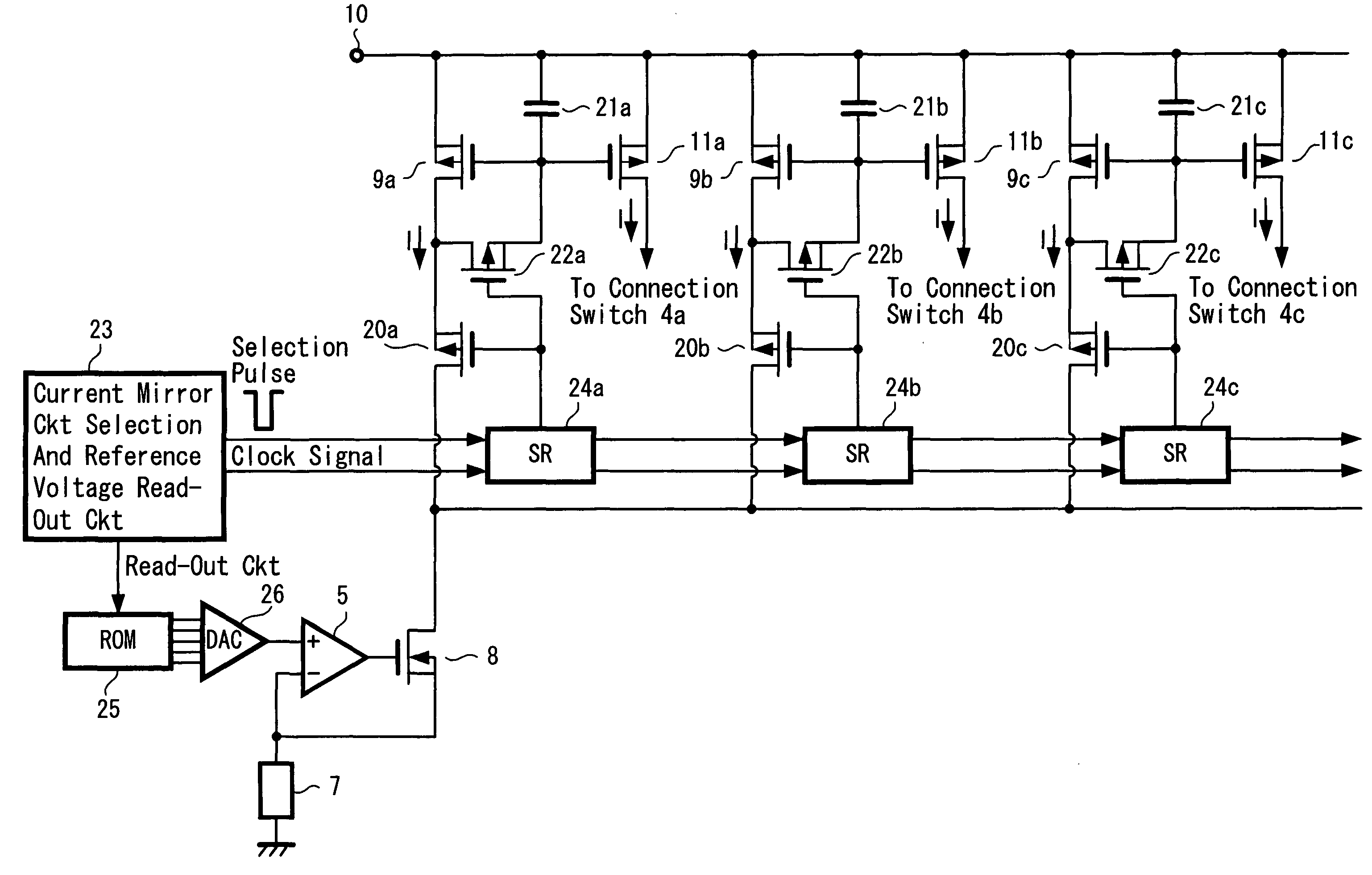
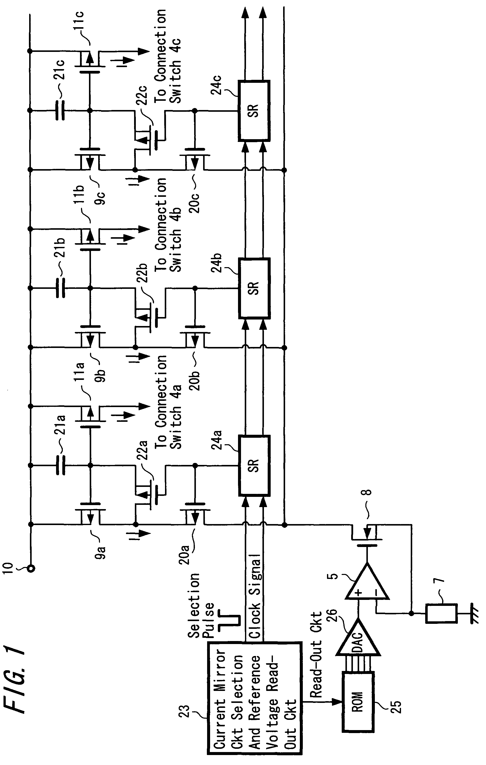
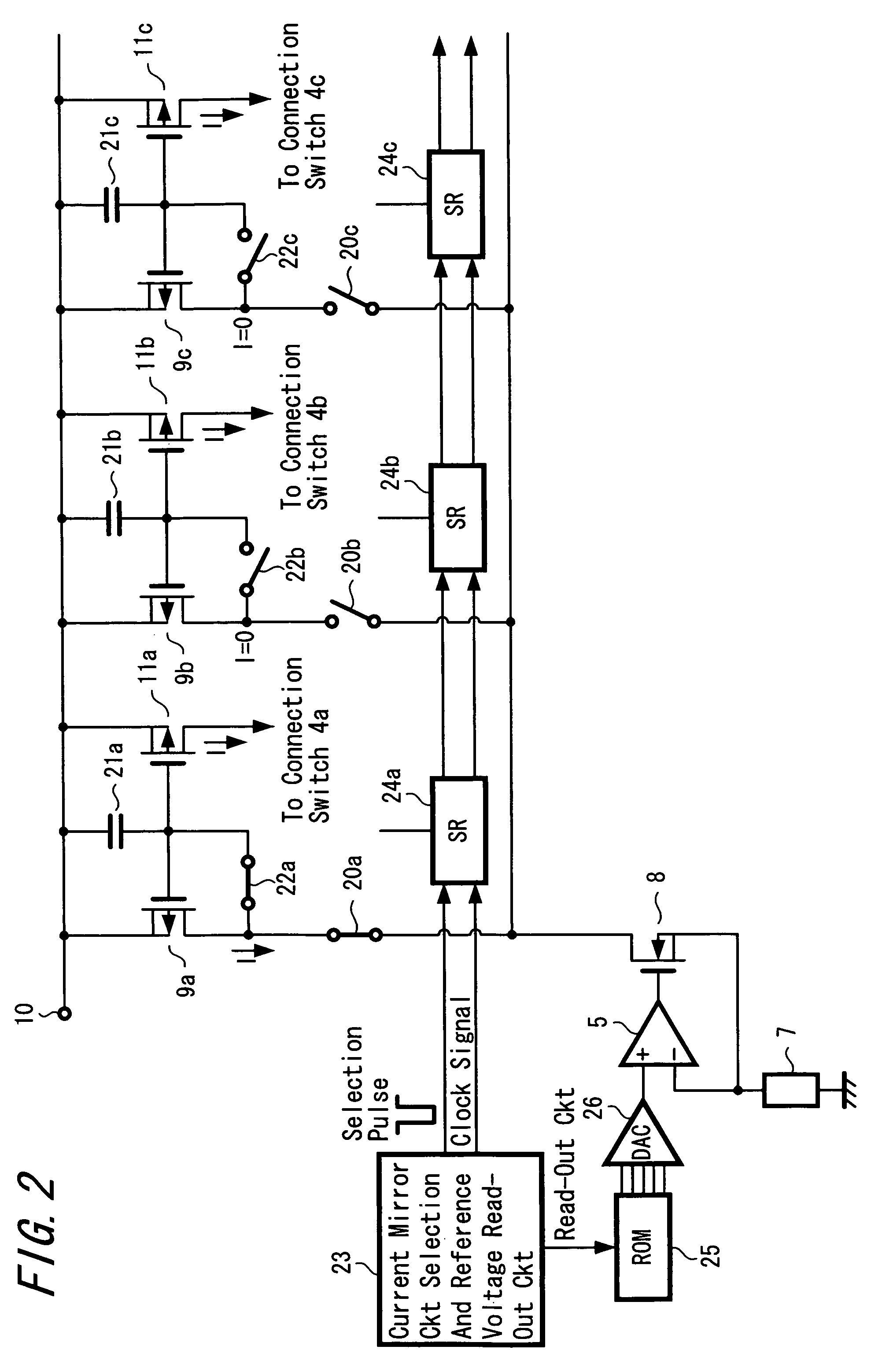
[0031]Hereinafter, it will be explained with respect to the best mode example in order to carry out a constant current drive device of the present invention with reference to FIG. 1, FIG. 2 and FIG. 3. In these FIG. 1 and FIG. 2, portions corresponding to those in FIG. 6 are shown by putting the same reference numerals.

[0032]In this example, as shown in FIG. 1, an inversion input terminal − of the operational amplifier circuit 5 which constitutes a constant current generation unit is grounded through the resistor 7. An output terminal of the operational amplifier circuit 5 is connected to the gate of the n-type field effect transistor 8 and the source of the field effect transistor 8 is connected to the inversion input terminal − of the operational amplifier circuit 5.

[0033]Also, in this example, the drain of the field effect transistor 8 constituting the constant current generation unit is connected to respective drains of p-type field effect transistor 20a, 20b and 20c constitutin...


PUM


Abstract

An object of the present invention is to eliminate fluctuation in the value of the constant current I even if there is characteristic fluctuation in field effect transistors and at the same time, to improve the power consumption. There are provided with a plurality of current mirror circuits consisting of those on the reference side and on the mirror side; current holding capacitors 21a, 21b and 21c provided on the respective mirror sides of the plurality of current mirror circuits; sequential selection means 23, 24a, 24b and 24c for selecting the plurality of current mirror circuits sequentially by a constant period; first switching means 22a, 22b and 22c for connecting respective reference sides and mirror sides of the plurality of current mirror circuits; reference voltage change-over means 23, 25 and 26 for changing over reference voltages of constant current generation units 5, 7 and 8 such that currents on the mirror sides become constant in conformity with the selection period of the plurality of current mirror circuits; and second switching means 20a, 20b and 20c for connecting the constant current generation units 5, 7 and 8 to the reference sides of the plurality of current mirror circuits in conformity with the selection period.

Description

TECHNICAL FIELD[0001]The present invention relates to a constant current drive device preferably applied for driving a display device in which current drive devices such as organic electroluminescence devices (hereinafter, referred to as organic EL devices), light emitting diodes (hereinafter, referred to as LEDs) or the like are arranged in a matrix form.BACKGROUND ART[0002]In the past, there was proposed a display device in which current drive devices 1 such as organic EL devices, LEDs or the like are arranged in a matrix form as shown in FIG. 4. Although there is described a display device in the example of FIG. 4 in which the current drive devices 1 are in a matrix form by 3×3 units in order to simplify the explanation thereof, a picture display device in which they are in a matrix form, for example, by 500×500 units was realized practically.[0003]A line sequential drive is carried out for driving the display device in which the current drive devices 1 are arranged in a matrix f...

Claims


Application Information

Patent Timeline
Patent Type & Authority Patents(United States)
IPC IPC(8): H03B1/00
CPCG05F3/262G09G3/3283G09G3/32G09G3/3216G05F3/26
Inventor TANAKA, YOSHIMITSU
Owner SONY CORP
Why Eureka
Try Eureka