Polyhedral antenna and associated methods

a polyhedral antenna and polyhedral antenna technology, applied in the field of antennas, can solve the problems of limited gain bandwidth of this system and special challenges of low rcs antenna requirements, and achieve the effect of low radar cross section

Active Publication Date: 2010-10-05
HARRIS CORP
View PDF15 Cites 240 Cited by
  • Summary
  • Abstract
  • Description
  • Claims
  • Application Information

AI Technical Summary

Problems solved by technology

Gain bandwidth of this system is limited, due to the narrow bandwidth of the wire loop probe.
Low RCS antenna requirements may pose special challenges; antennas can be both an aperture for radiation and an aperture for scattering radar energy.

Method used


Image

  • Polyhedral antenna and associated methods
  • Polyhedral antenna and associated methods
  • Polyhedral antenna and associated methods

Examples


Embodiment Construction

[0032]The present invention will now be described more fully hereinafter with reference to the accompanying drawings, in which preferred embodiments of the invention are shown. This invention may, however, be embodied in many different forms and should not be construed as limited to the embodiments set forth herein. Rather, these embodiments are provided so that this disclosure will be thorough and complete, and will fully convey the scope of the invention to those skilled in the art. Like numbers refer to like elements throughout, and prime notation is used to indicate similar elements in alternative embodiments.

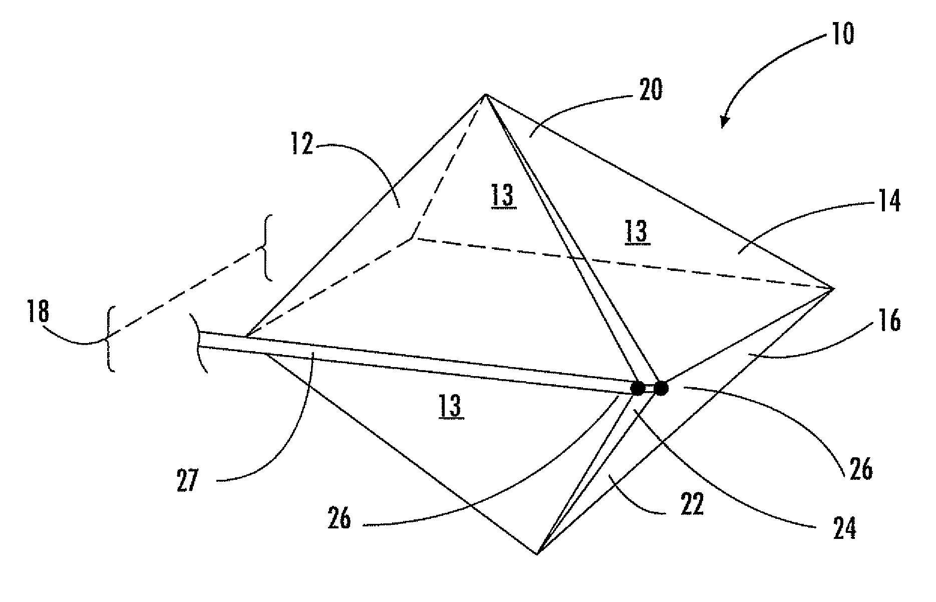
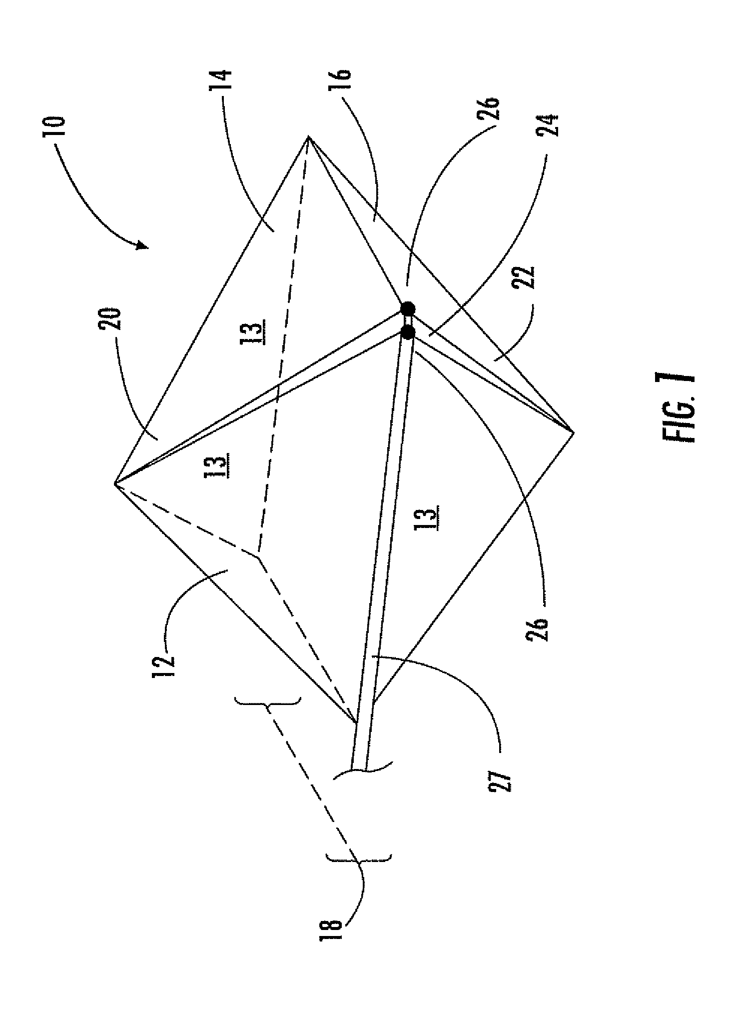
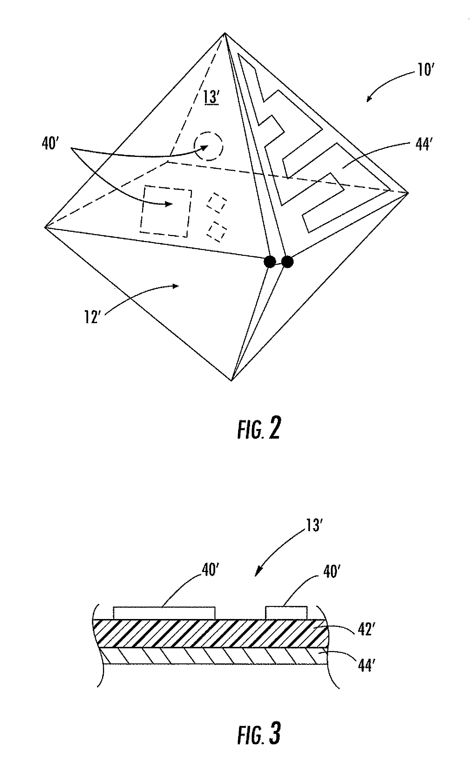
[0033]Referring initially to FIG. 1, a polyhedral loop antenna 10 in accordance with the present invention will be described. The polyhedral loop antenna 10 includes an electrically conductive antenna body 12 with first and second polyhedral body portions 14, 16 connected together at a medial portion 18 of the antenna body. First and second opposing ends 20, 22 have the med...


PUM

PropertyMeasurementUnit
electrical sizeaaaaaaaaaa
electrically conductiveaaaaaaaaaa
dielectricaaaaaaaaaa

Abstract

The antenna includes an electrically conductive antenna body having a polyhedral shape with opposing first and second ends and a medial portion therebetween. The medial portion of the electrically conductive antenna body is wider than the opposing first and second ends thereof, and the electrically conductive antenna body has a slot therein extending from at least adjacent the first end to at least adjacent the second end. The polyhedral antenna has an omnidirectional pattern, is horizontally polarized and broad in bandwidth above a lower cutoff frequency.

Description

FIELD OF THE INVENTION[0001]The present invention relates to the field of antennas, and more particularly, this invention relates to omnidirectional antennas, slot antennas, horizontal polarization antennas, radar scattering, and related methods.BACKGROUND OF THE INVENTION[0002]An antenna is a transducer that converts radio frequency electric current to electromagnetic waves that are then radiated into space. The antenna may also convert electromagnetic waves into electric current, or even be a reflector of waves like a RADAR target. The electric field or “E” plane determines the polarization or orientation of the radio wave. In general, most antennas radiate either linear or circular polarization.[0003]A linearly polarized antenna radiates in one plane. In a circularly polarized antenna, the plane of polarization rotates in a circle making one complete revolution during one period of the wave. An antenna is said to be vertically polarized (linear) when its electric field is perpend...

Claims


Application Information

Patent Timeline
Patent Type & Authority Patents(United States)
IPC IPC(8): H01Q9/28H01Q13/00
CPCH01Q7/00Y10T29/49016
Inventor PARSCHE, FRANCIS EUGENETEBBE, DENNIS LEE
Owner HARRIS CORP
Why Eureka
Try Eureka