Direct conversion receiver and DC offset reducing method

Inactive Publication Date: 2007-01-30
PANASONIC CORP
View PDF17 Cites 56 Cited by
  • Summary
  • Abstract
  • Description
  • Claims
  • Application Information

AI Technical Summary

Benefits of technology

[0019]The present invention aims to overcome problems newly found out by the inventor of the present invention, and it is an object of the present invention to provide a direc

Problems solved by technology

However, when the cut-off frequency of a high-pass filter is made higher than a predetermined value, i.e., the cut-off frequency is brought close to the frequency of a modulated signal (received signal) comp

Method used


Image

  • Direct conversion receiver and DC offset reducing method
  • Direct conversion receiver and DC offset reducing method
  • Direct conversion receiver and DC offset reducing method

Examples


first embodiment

[0056](First Embodiment)

[0057]It is a feature of the present invention to detect a gain variation amount of a variable gain amplifier, and switch a time constant of a high-pass filter.

[0058]Prior to explanations of a configuration and operation of a direct conversion receiver of the present invention, referring to FIGS. 1 to 9, reasons will be described below that switching of cut-off frequency of a high-pass filter is effective at reducing a DC offset in a direct conversion receiver.

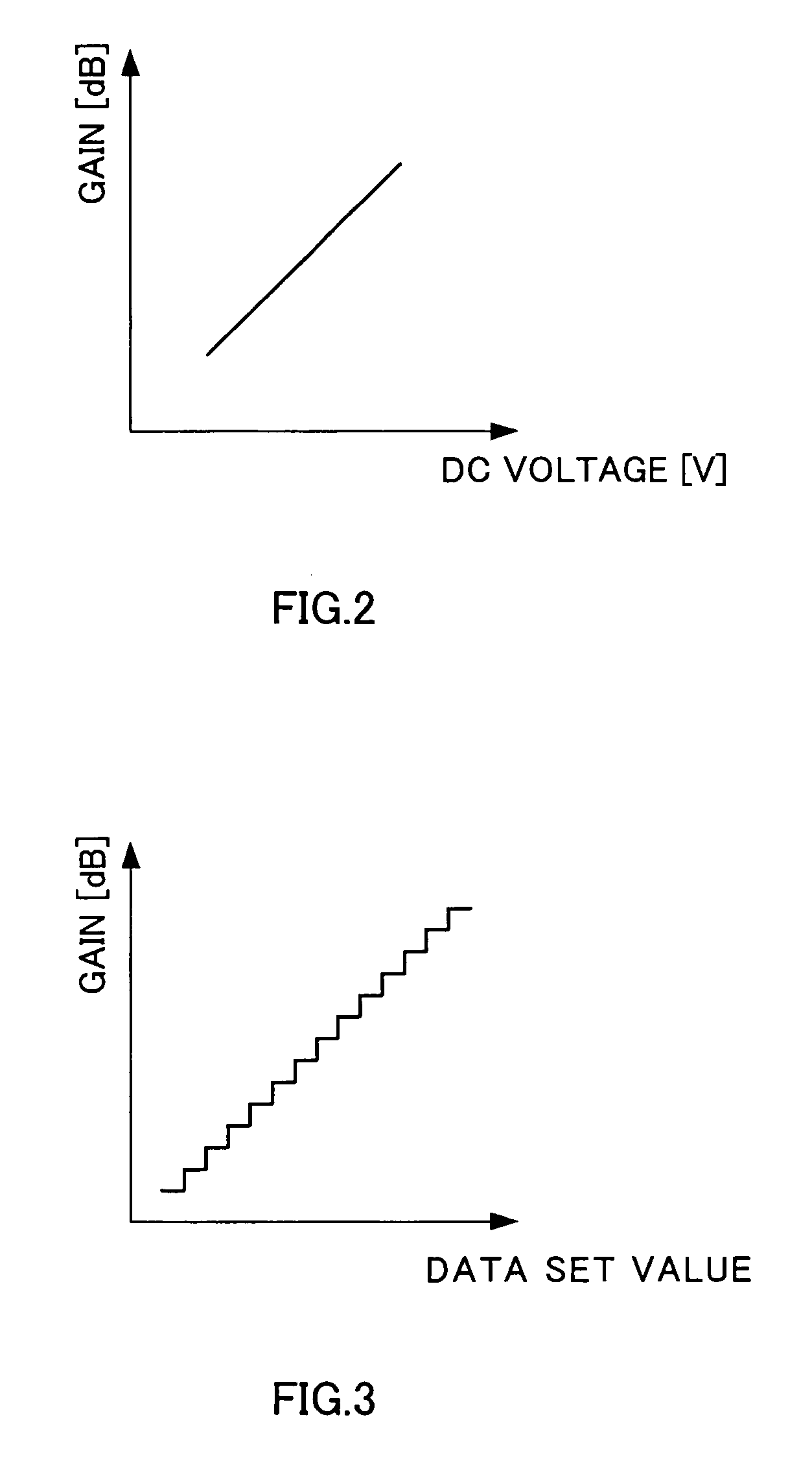
[0059]FIG. 2 shows gain characteristics of a variable gain amplifier when the gain of the variable gain amplifying circuit is varied using an analog control voltage, and FIG. 3 shows gain characteristics of a variable gain amplifier when a digital control signal (serial data) is used to control.

[0060]The invention according to this embodiment can be implemented in a variable gain amplifying circuit with characteristics that the gain varies linearly as shown in FIG. 2 or 3.

[0061]FIG. 4 shows the relation...

second embodiment

[0131](Second Embodiment)

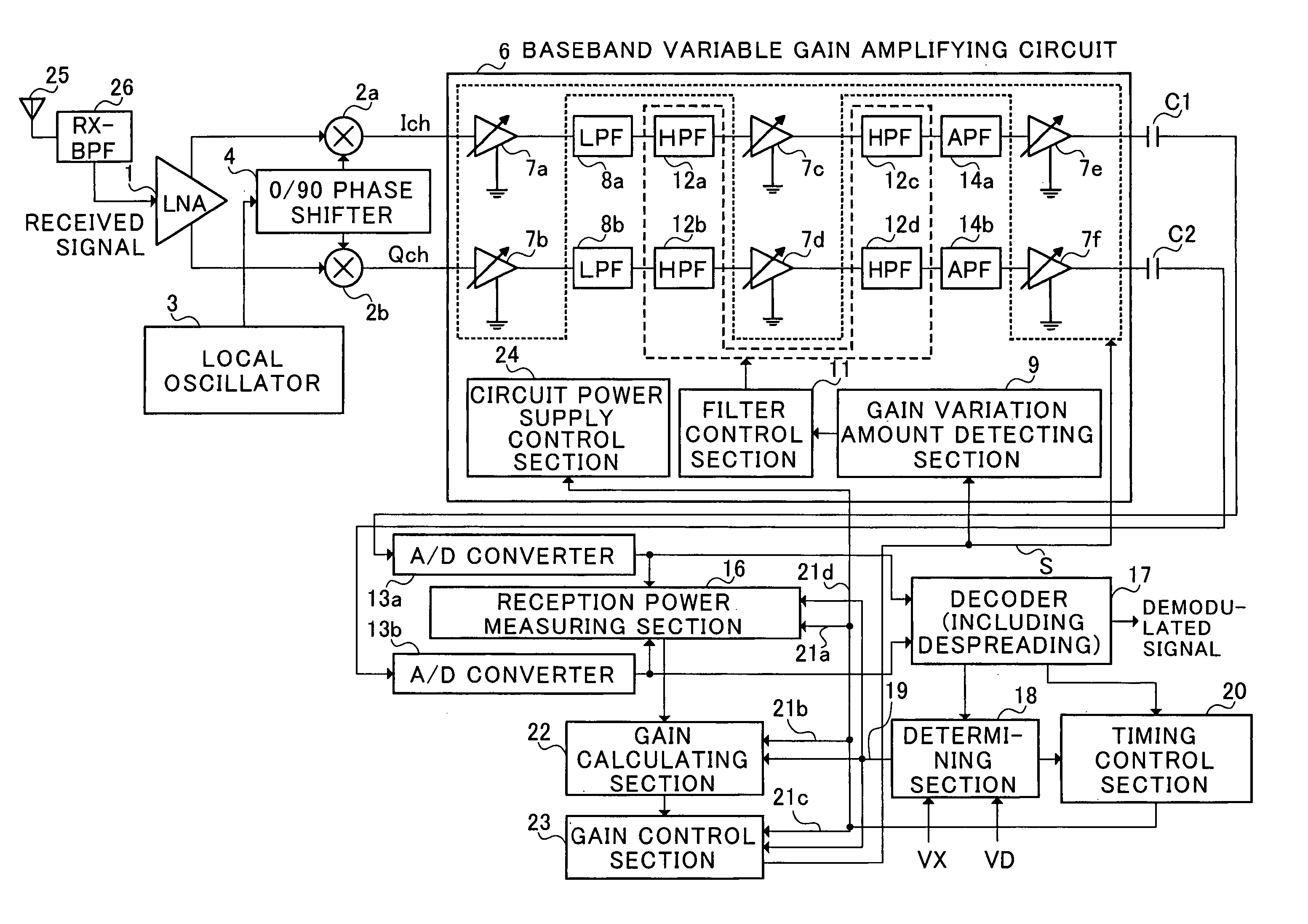
[0132]FIG. 16 is a block diagram illustrating a configuration of a direct conversion receiver (W-CDMA receiver provided with an internal AGC circuit) according to the second embodiment of the present invention.

[0133]The primary configuration of the receiver according to this embodiment is almost the same as in the first embodiment (FIG. 10). In this embodiment, features are that switching of time constant of the high-pass filter is controlled based on AGC mode signal 19 output from determining section 18 and timing control signal 21e from timing control section 20, and that gain variation amount detecting 9 in FIG. 10 is eliminated.

[0134]As described above, the switching of cut-off frequency of the high-pass filter is required when AGC does not converge at all, for example, immediately after the power is supplied, and the loop needs to be repeated at high speed to adapt the gain of the variable gain amplifier to propagation environments at high speed.

[0135]T...

third embodiment

[0143](Third Embodiment)

[0144]Various methods are considered as methods for implementing in actual circuitry the switching of cut-off frequency of the high-pass filter that is the feature of the present invention. This embodiment describes various modifications of the configuration for switching the cut-off frequency that are not disclosed in the above-mentioned embodiments.

[0145]FIG. 18 illustrates an example where a direct conversion receiver controls the gain of the variable gain amplifier using digital data (serial data) instead of using an analog control signal.

[0146]Gain control section 23 outputs a gain control signal (serial data). For example, the serial data has a width of 16 bits, and among the bits, 10 bits are of gain data, while remaining 6 bits are available for use in various control.

[0147]Then, the control data is “1” when switching the cut-off frequency of the high-pass filter. On the contrary, when the control data is “0”, the switching of cut-off frequency is not...


PUM


Abstract

A determining section (18) and gain variation amount detecting section (9) detect a period having a possibility of a DC-component offset in an internal circuit of a direct conversion receiver increasing beyond an allowable value due to AGC operation, and during the period, a cut-off frequency of each of high-pass filters (12a to 12d) is set at a frequency higher than that in general operation, thereby rapidly converging transient responses of signals passed through the high-pass filters, while controlling precisely operation timings of reception power measuring section (16), gain calculating section (22), gain control section (23) and circuit power supply control section (24) composing an AGC loop, whereby the DC offset is prevented from increasing and stable circuit operation is assured. It is thereby possible to achieve further reductions in size and power consumption of a CDMA receiver using the direct conversion receiver.

Description

TECHNICAL FIELD[0001]The present invention relates to a DC (Direct Current) offset reducing method, an AGC (Automatic Gain Control) circuit in a direction conversion receiver, a CDMA (Code Division Multiple Access) receiver and a baseband variable gain amplifying circuit.BACKGROUND ART[0002]A direct conversion receiver is a receiver that multiplies a RF signal received in an antenna by a carrier (local signal) of substantial same frequency and thus directly converts the RF signal into a baseband signal without eliminating conversion into a signal of intermediate frequency, and contributes to miniaturization, weight reduction and low power consumption in a radio receiver.[0003]The direction conversion receiver is described in, for example, Japanese Laid-Open Patent Publication No.H10-247953.[0004]However, in the direct conversion receiver, there is a problem that a direct current offset (hereinafter referred to as “DC offset”) specific to the circuitry arises.[0005]As measures agains...

Claims


Application Information

Patent Timeline
IPC IPC(8): H04B1/26H03G3/30H04B1/16H04B1/30H04B1/707H04J13/00H04L25/06H04L27/14H04L27/38
CPCH03G3/3068H04B1/30H04L27/3809H04L25/06H04B2201/70707H03G3/30
Inventor MATSUMOTO, HIDENORIOBARA, TOSHIO
Owner PANASONIC CORP
Why Eureka
Try Eureka