Light management films for displays

a technology of light management and film, applied in the field of microfabrication methods and systems, can solve the problems of affecting the overall production yield of the product,

Inactive Publication Date: 2010-10-05
BRIGHT VIEW TECHNOLOGIES CORPORATION
View PDF12 Cites 43 Cited by
  • Summary
  • Abstract
  • Description
  • Claims
  • Application Information

AI Technical Summary

Benefits of technology

[0025]Some embodiments of the present invention use sheets of, for example, photopolymer plastic, in which appropriately sized shapes have been formed, which can act as sieves and / or moulds for forming and / or selecting micron-sized particles. In some embodiments, these sheets can be on the order of 1 sq m and thus may contain billions of features for forming and / or sieving particles. Monodispersed collections of particles may thereby be produced efficiently. These embodiments are illustrated, for example, in FIG. 16.

Problems solved by technology

Producing particles of a tightly controlled size and then sieving them to produce monodispersed collections may be time consuming and / or expensive.
Current methods for sieving the particles to obtain accurately monodispersed collections may be time consuming.
In the replication of large stampers, this can be a difficult and time consuming process while errors in this process can significantly degrade overall production yields.
High powered Infrared (IR) Lasers can be particularly difficult and dangerous to use since the radiation beam is not visible.
Apart from expensive and cumbersome solutions such as IR goggles, conventionally a material known as “burn paper” is used to identify the beam location.
Since it is not desirable that smoke or particles from the burn enter the atmosphere around the laser, potentially degrading optical components, the paper is normally held in a sealed plastic bag.
The image quality of many display devices can be degraded by the effects of ambient light reflecting from the display surface and interfering with the display image.
In extreme cases, for example when viewing a computer display in daylight conditions, ambient light may completely “wash out” the image, rendering it unviewable.
Anti-reflection coatings are available in certain instances, but these may be costly, may be difficult to apply to materials such as plastics, and / or may themselves interfere with image quality.
A second problem which may adversely affect the performance of displays is the inability to distribute the available light emerging from the display to the various points or spatial positions at which viewers may wish to use or view the display.
Diffusers which are isotropic thus, in effect, may waste a great deal of illumination by throwing it into positions where viewers are more unlikely to be found.
A third problem which may adversely affect screen performance is the presence of artifacts such as moiré patterns or other instances of aliasing, as well as speckle and related artifacts related to coherence phenomena.
These problems, although subtle, may be pervasive and may account for an overall perception that images produced by a display lack clarity or sharpness.

Method used


Image

  • Light management films for displays
  • Light management films for displays
  • Light management films for displays

Examples


example 1

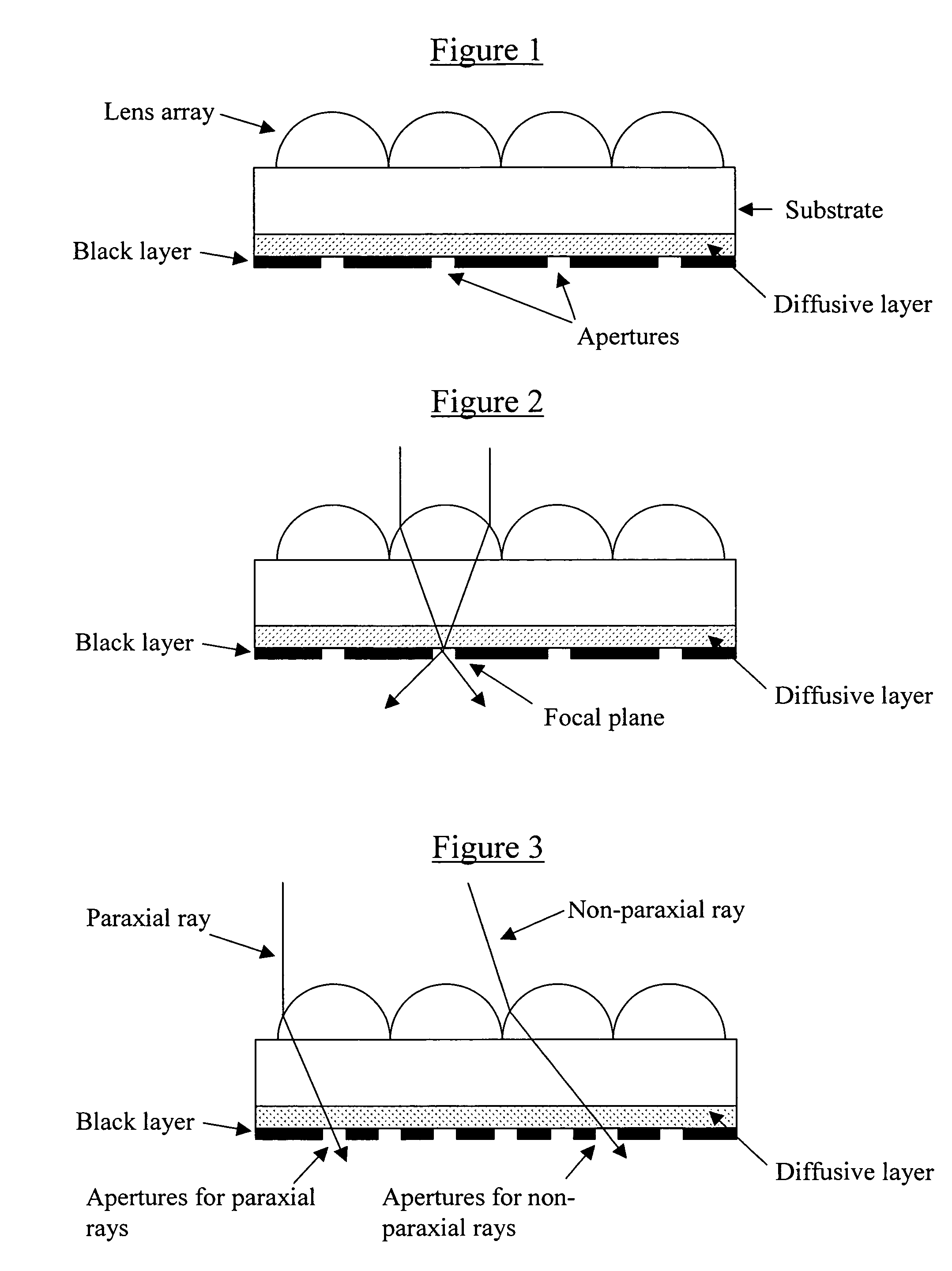
[0102]A plastic web stock was coated with both the diffusive layer and black layer. A lens array was formed on the web stock using a stamper. The lens arrays were then irradiated with coherent radiation to create self-aligned apertures. This exposure additionally created other apertures related to the thickness of the dispersion layer and the size and character of the apertures were directly related to this film thickness and power incident on the surface. Incident power ranged from 250 to 450 mJ. This example is illustrated in FIGS. 1-3.

example 2

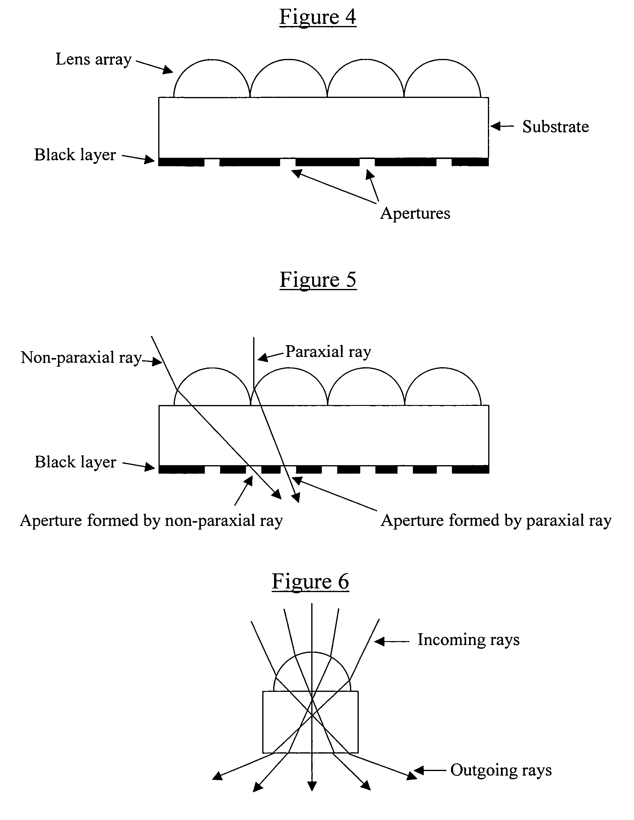
[0103]Plastic web stock was coated with a black layer. A lens array was formed on this web stock from a stamper. The lens arrays were the irradiated with coherent radiation at angles both of normal incidence and at 15 and 30 degrees off of normal in both directions (FIG. 6). The result was the creation of 5 distinct apertures per lens with the only visible light observed in a microscope objective being that light incident and directed in the same direction as the exposed light ray example.

[0104]The above example was further repeated with 3 incident laser light beams, one normal and two at + / −30 degrees incident angles. Again the result was the formation of distinct apertures which accumulated light in the direction of aperture creation. This example is illustrated in FIGS. 4-6.

example 3

[0105]Samples were created to display elongated apertures in front of elongated lens shapes. These elongated apertures exhibited both an increased transmissivity and an increase in viewing angle, up to 20 degrees in the test samples. The above light control examples were created in a plastic web stock coated with a black layer on one side and on the other side of which a lens array was replicated off of a stamper. The exposure with a laser created self-aligned apertures and the shape of the aperture was further elongated by increase intensity of the exposure to the laser beam and at exposure intensities of 350 to 400 mJ. This example is illustrated in FIGS. 7-9.


PUM

PropertyMeasurementUnit
sizesaaaaaaaaaa
widthaaaaaaaaaa
lengthaaaaaaaaaa

Abstract

Microlens arrays include a substrate, an array of microlenses on a first side of the substrate and an aperture mask on a second side of the substrate. The aperture mask includes an array of apertures at optical axes of the lenses. A second array of apertures may be included in the aperture mask at randomized positions therein. The randomized apertures may be provided in the aperture mask by providing a diffusive layer between the aperture mask and the substrate, and directing coherent radiation through the lens array, the diffusive layer and aperture mask.

Description

RELATED APPLICATIONS[0001]This application claims the benefit of U.S. Provisional Application Ser. Nos. 60 / 544,036, filed Feb. 12, 2004, entitled Microlens Arrays With Aperture Masks Having Randomized Apertures and Methods of Fabricating Same; 60 / 544,018, filed Feb. 12, 2004, entitled Microlens Arrays With Aperture Masks Having Multiple Apertures Per Lens and Methods of Fabricating Same; 60 / 544,027, filed Feb. 12, 2004, entitled Microlens Arrays With Aperture Masks Having Varying Aperture Shapes and Methods of Fabricating Same; 60 / 544,026, filed Feb. 12, 2004, entitled Microlens Arrays With Aperture Masks Having Apertures That Include Diffusive Materials and Methods of Fabricating Same; 60 / 546,819, filed Feb. 19, 2004, entitled Microlens Arrays With Contrast Enhancing and / or Light Management Films for Use With LCD or Other Displays; 60 / 545,875, filed Feb. 19, 2004, entitled Retroreflectors Including Microlens Arrays and / or Optical Mask Layers, and Methods of Fabricating Retroreflect...

Claims


Application Information

Patent Timeline
Patent Type & Authority Patents(United States)
IPC IPC(8): G02B27/10G02F1/1335
CPCG02B3/0031G02B3/0056G02B6/0036G02B6/0046G02B6/005G02B6/0055G02F1/133526
Inventor FADEL, EDWARDFREESE, ROBERT P.GARDNER, RICHARD N.NUZUM, MICHELE E.REED, DAVID L.RINEHART, THOMAS A.WOOD, ROBERT L.
Owner BRIGHT VIEW TECHNOLOGIES CORPORATION
Why Eureka
Try Eureka