Parallel-sequential turbocharging for improved exhaust temperature control

a parallel-sequence, exhaust temperature control technology, applied in the direction of electric control, combustion engines, machines/engines, etc., can solve the problems of low device efficiency, difficult to maintain the exhaust temperature within a proper range, limited engine power, etc., to achieve the effect of reducing turbo lag, increasing air induction, and maintaining peak boosting performan

Inactive Publication Date: 2010-10-12
FORD GLOBAL TECH LLC
View PDF14 Cites 7 Cited by
  • Summary
  • Abstract
  • Description
  • Claims
  • Application Information

AI Technical Summary

Benefits of technology

[0001]Internal combustion engines are commonly used in today's automobiles. Since inducted air is used to burn fuel and produce power in this type of engine, engine power may be limited by the amount of air that can be inducted into the combustion chamber. Turbochargers may be used to increase the air inducted to the combustion chamber compared with a naturally aspirated system. Further, some automobiles may employ a dual turbocharger system, which can reduce turbo lag while maintaining peak boosting performance by allowing the operation of a single turbocharger at lower engine speed and the operation of dual turbochargers at higher engine speed.
[0005]By providing both a higher heat loss and a lower heat loss path with a crossover that allows communication between the two paths, and by providing a mechanism to control the flow through the higher heat loss and the lower heat loss paths, the exhaust temperature may be better controlled to increase the efficiency of the emission control device operation in a dual turbocharger environment. Under certain conditions, for example, when the engine is operating at a lower load / speed, the exhaust flow through the higher heat loss path is reduced and the exhaust flow through the lower heat loss path is increased to reduce heat loss; while under certain other conditions, for example, when the engine is operating at a higher load / speed, the exhaust flow through the higher heat loss path is increased and the exhaust flow through the lower heat loss path is decreased to increase heat loss from the exhaust.
[0006]Further, by placing the crossover between the higher heat loss path and the lower heat loss path upstream of both turbochargers, it is possible to achieve (1) a faster boost response because only one turbocharger has to be spun up and this turbocharger will receive twice as much airflow compared to if both turbochargers have to be spun up, and (2) a faster exhaust warm-up because all exhaust flows through the lower heat loss path and the cooling that may result from air expansion in the second turbocharger is reduced.
[0007]As such, it is possible to provide an internal combustion engine that has a dual turbocharger system and an emission control device with mechanisms to control the exhaust temperature for improved operation of the emission control device.

Problems solved by technology

Since inducted air is used to burn fuel and produce power in this type of engine, engine power may be limited by the amount of air that can be inducted into the combustion chamber.
However, one issue associated with such dual turbocharger systems and possibly other dual turbocharger systems is that it may be difficult to maintain the exhaust temperature within a proper range for the optimal operation of a device in the emission control system for reducing emissions in the exhaust.
For example, if the exhaust temperature is too cold, the efficiency of the device may be low; and if the exhaust temperature is too hot, the device may degrade physically or chemically in the example of a catalytic device.
During some conditions, for example when the engine has just been started or when the engine is operated at a low speed, the exhaust temperature may be too low for efficient operation or catalytic conversion.
Yet during other conditions, for example when the engine is operated at a high speed or load, the exhaust temperature may be too high, which may cause a catalyst to degrade.

Method used


Image

  • Parallel-sequential turbocharging for improved exhaust temperature control
  • Parallel-sequential turbocharging for improved exhaust temperature control
  • Parallel-sequential turbocharging for improved exhaust temperature control

Examples


first embodiment

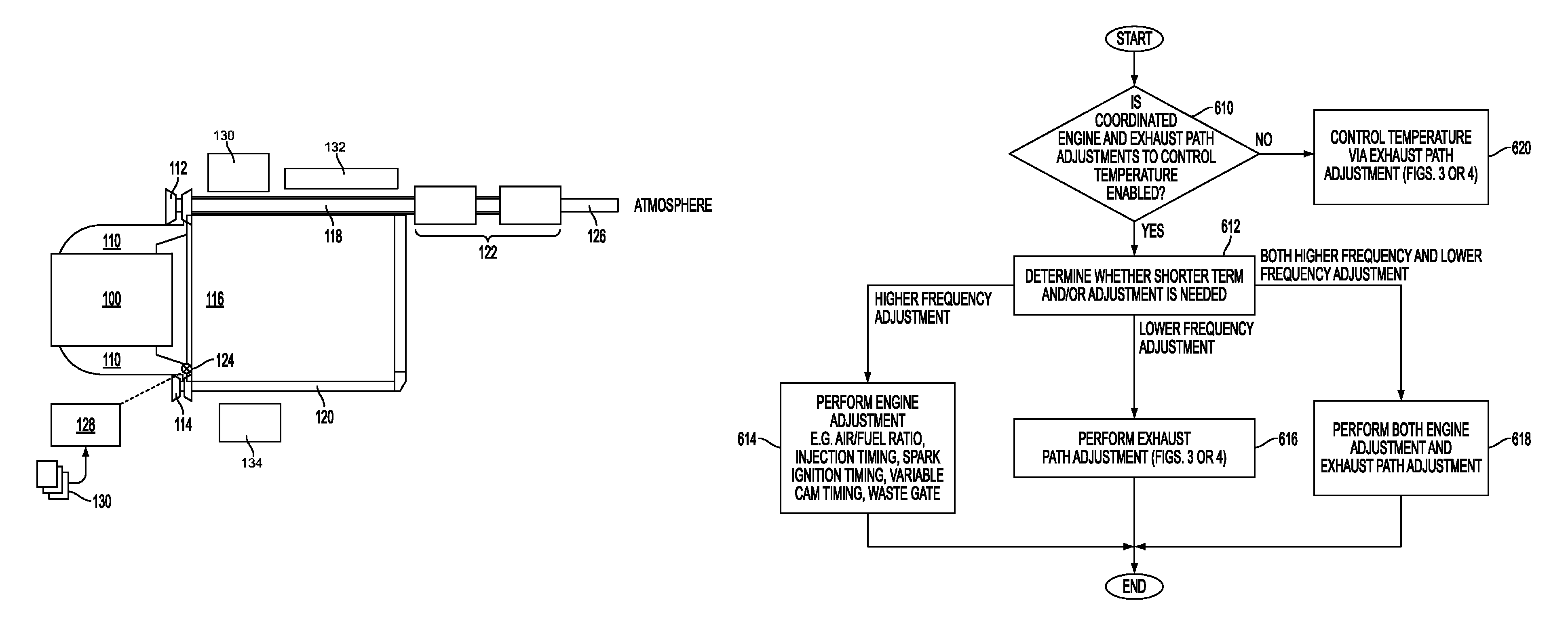
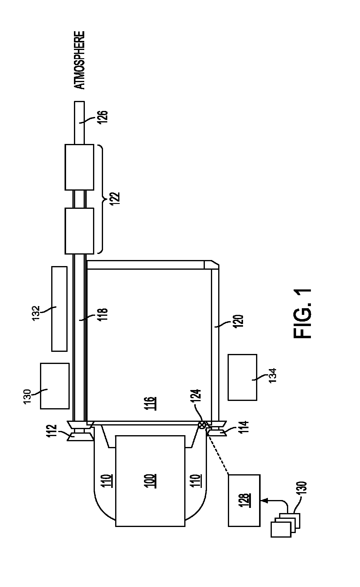
[0015]As illustrated in FIG. 1, an internal combustion engine with a dual turbocharger system in accordance with a first embodiment includes a multi-cylinder engine block 100, an exhaust manifold 110, a first turbocharger 112, a second turbocharger 114, a lower heat loss path 118, a higher heat loss path 120, an emission control device 122, an exhaust tail-pipe 126 that opens into the atmosphere, a crossover 116 that provides a passage between the lower heat loss path 118 and the higher heat loss path 120, and a control mechanism 124 that can control the exhaust flow through the crossover 116.

[0016]The exhaust manifold 110 is connected to the engine exhaust outlets and includes a first portion connected to a first group of engine cylinders and a second portion connected to a second group of engine cylinders. The exhaust manifold 110 is also connected to the turbochargers with the first portion connected to the first turbocharger 112 and the second portion connected to the second tur...

second embodiment

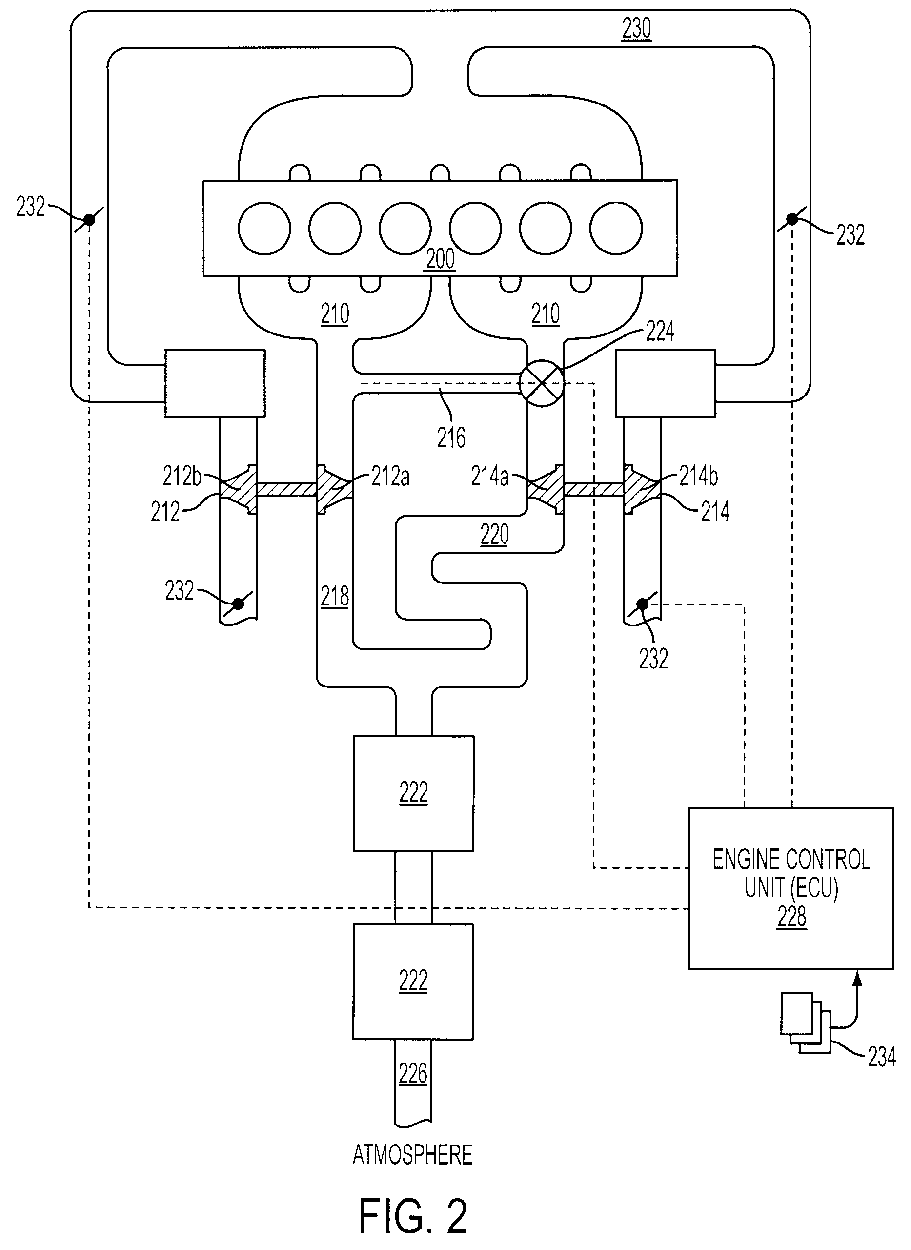
[0028]FIG. 2 illustrates an engine system with a dual turbocharger system in accordance with a second embodiment includes an in-line engine block 200, an engine intake conduit 230, an exhaust manifold 210, a first turbocharger 212, a second turbocharger 214, a lower heat loss path 218, a higher heat loss path 220, an emission control device 222, an exhaust tail-pipe 226 that opens into the atmosphere, a crossover 216 that provides a passage between the lower heat loss path 218 and the higher heat loss path 220, a control mechanism 224 that can control the exhaust flow through the crossover 216, and an engine control unit (ECU) for controlling the operation of the mechanism 224, sometimes in coordination with various engine throttles 232.

[0029]In this particular embodiment, the control mechanism 224 is located immediately upstream of the lower heat loss path and serves to cut off the exhaust flow through the lower heat loss path when it is in a closed position, and to enable various ...


PUM


Abstract

A method is described for controlling the exhaust temperature of an emission controlling device in the exhaust using both a higher heat loss path and a lower heat loss path along with parallel / sequential turbocharging. The exhaust path is adjusted based on a rate of change of temperature control error.

Description

BACKGROUND AND SUMMARY[0001]Internal combustion engines are commonly used in today's automobiles. Since inducted air is used to burn fuel and produce power in this type of engine, engine power may be limited by the amount of air that can be inducted into the combustion chamber. Turbochargers may be used to increase the air inducted to the combustion chamber compared with a naturally aspirated system. Further, some automobiles may employ a dual turbocharger system, which can reduce turbo lag while maintaining peak boosting performance by allowing the operation of a single turbocharger at lower engine speed and the operation of dual turbochargers at higher engine speed.[0002]One type of dual turbocharger system is described in U.S. Pat. No. 5,186,005. In this particular dual turbocharger system, twin turbochargers are arranged in a parallel fashion with respect to the engine, and a crossover pipe connects the twin turbochargers. One turbocharger is operated at low engine load / speed wh...

Claims


Application Information

Patent Timeline
Patent Type & Authority Patents(United States)
IPC IPC(8): F02B33/44F02B33/00F01N1/00F01N13/14
CPCF01N13/107F02B37/001F02B37/007F02B37/18F02D41/0007F02D41/0082F01N13/0093F01N13/009F02D41/1446F02D2041/002Y02T10/144Y02T10/12
Inventor GOEBELBECKER, MICHAELMURPHY, KEVIN
Owner FORD GLOBAL TECH LLC
Why Eureka
Try Eureka