

Optical information recording medium and optical information reproducing method
a technology of optical information and recording medium, which is applied in the field of large-capacity optical disc technique, can solve the problems of difficult to obtain satisfactory signal amplitude, difficult to obtain satisfactory signal noise ratio (snr), conventional super-resolution techniques, etc., and achieve the effect of improving signal amplitude and reducing data error ra
- Summary
- Abstract
- Description
- Claims
- Application Information
AI Technical Summary
Benefits of technology
Problems solved by technology
Method used
Image

Examples
first embodiment
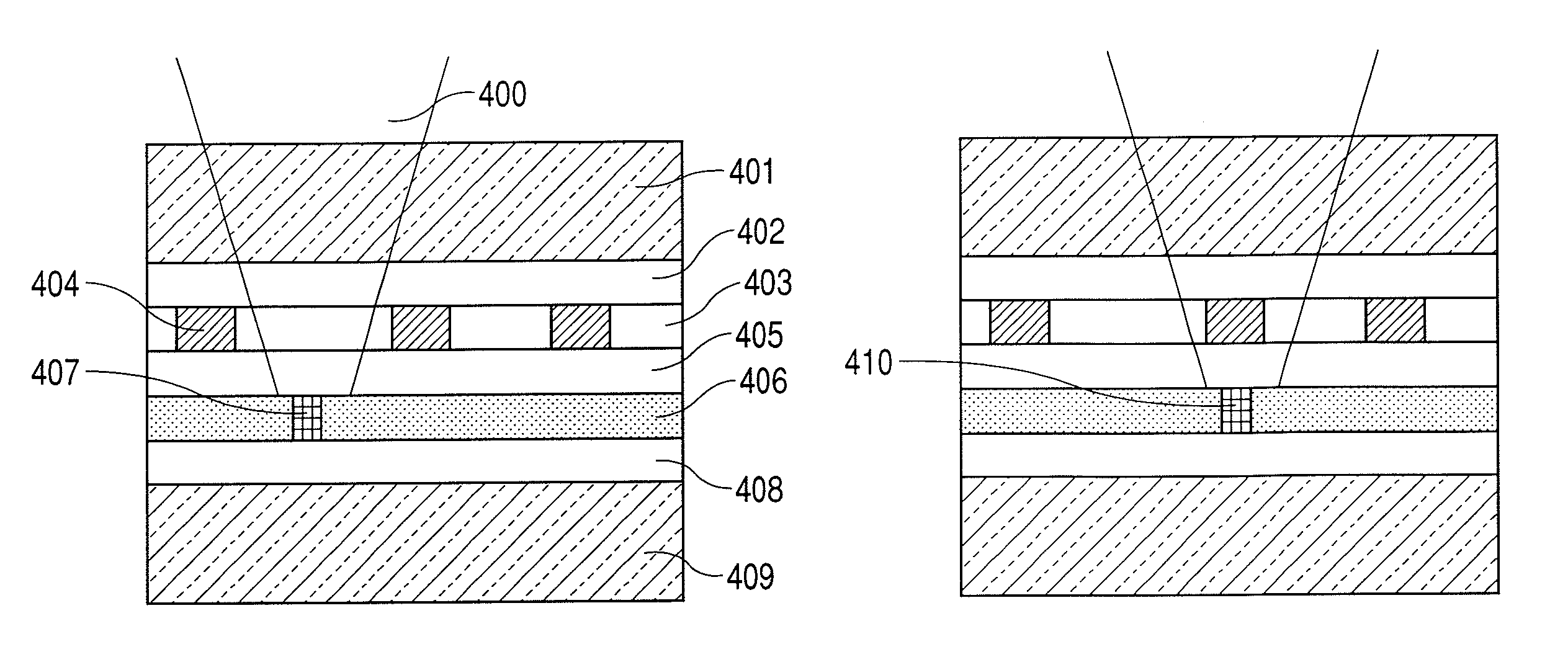
[0034]At first, a case of recording type thin film super-resolution will be described with reference to FIGS. 4A and 4B.
[0035]In this embodiment, two discs were manufactured. One (structure A) of the discs was designed in accordance with the guidance of the conventional techniques. The other disc (structure B) was designed in accordance with the guidance of the present invention. Each of the discs was composed as follows sequentially from a side near to the light incidence side.
[0036]Structure A: ultraviolet curable resin 100 μm / ZnS—SiO2(50 nm) / GeSbTe(20 nm) / ZnS—SiO2(20 nm) / Ga(40 nm) / ZnS—SiO2(50 nm) / Al(100 nm) / polycarbonate substrate
[0037]Structure B: ultraviolet curable resin 100 μm / ZnS—SiO2(30 nm) / GeSbTe(20 nm) / ZnS—SiO2(30 nm) / Ga(10 nm) / ZnS—SiO2(30 nm) / Al(100 nm) / polycarbonate substrate
[0038]Here, GeSbTe corresponds to the recording film 403 and Ga corresponds to the super-resolution film 406. This disc obtains the super-resolution effect by melting Ga with an incident light. In t...
second embodiment
[0046]Next, the thin film super-resolution ROM disc shown in FIGS. 5A and 5B will be described.
[0047]Similarly to the first embodiment, a conventionally structured disc (structure A) and a disc of the present invention (structure B) were manufactured.
[0048]Structure A: ultraviolet curable resin 100 μm / ZnS—SiO2(30 nm) / GeSbTe(20 nm) / ZnS—SiO2(30 nm) / polycarbonate substrate
[0049]Structure B: ultraviolet curable resin 100 μm / ZnS—SiO2(20 nm) / GeSbTe(30 nm) / ZnS—SiO2(30 nm) / Ag(42 nm) / polycarbonate substrate
[0050]Each of the polycarbonate substrates has pits 507 corresponding to data as shown in FIGS. 5A and 5B. The recorded pit pattern is 1-7 modulated random pattern data of which minimum mark length was 100 nm. The pits 507 were about 41 nm in depth and 100 nm in width. The GeSbTe corresponds to the super-resolution film 503.
[0051]Similarly to the first embodiment, measurements were done for the reflectivity, signal level, and data error rate of the discs. Each disc drive configuration is t...
third embodiment
[0054]Next, a pit type super-resolution disc will be described with reference to FIGS. 7A and 7B.
[0055]At first, how the disc shown in FIGS. 7A and 7B was manufactured will be described.
[0056]Recorded pits were formed on a substrate 706 using an electron beam drawing device. Electron beam resist was coated on the Si substrate and focused electron beam pulses were irradiated on the specimen that was rotated to expose the resist. The shortest mark length of those pits was 50 nm. Thus 1-7 modulated random patterns were formed. Pits were formed in the exposed area in a development process. After that, a CF4 gas was used to form pits at a depth of 40 nm on the Si substrate in a reactive ion etching process and the residual electron beam resist was removed. The Si substrate obtained such way is referred to as a Si original disc. A Ni-plated stamper was manufactured from the original disc. The stamper having a high temperature was pressed on a disc substrate that was 1.1 mm in thickness an...
PUM
| Property | Measurement | Unit |
|---|---|---|
| diameter | aaaaa | aaaaa |
| diameter | aaaaa | aaaaa |
| diameter | aaaaa | aaaaa |
Abstract
Description
Claims
Application Information