Microscope system

a microscope and system technology, applied in the field of microscope systems, can solve the problems of complex apparatus construction, insufficient focus control acquisition by the apparatus construction, and inability to achieve sufficient focus control precision in the apparatus construction, and achieve the effect of high precision and enhanced precision of focus control information so acquired

Inactive Publication Date: 2010-10-12
HAMAMATSU PHOTONICS KK
View PDF19 Cites 13 Cited by
  • Summary
  • Abstract
  • Description
  • Claims
  • Application Information

AI Technical Summary

Benefits of technology

[0009]The present invention has been implemented to solve the above problem, and has an object to provide a microscope system which can suitably carry out focus control when an image of a sample is acquired.
[0012]Furthermore, in the above described system, the focus control image pickup means is constructed by the first image pickup means and the second image pickup means which are designed so that the optical path lengths thereof vary along a predetermined variation direction at different variation rates. A focus measurement is carried out by using two kinds of images acquired by these image pickup means, whereby it is possible to acquire focus control information with high precision when images of the sample are acquired. If the focus control information thus acquired is used, focus control can be suitably performed when the images of the sample are acquired. The first image pickup means and the second image pickup means constituting the focus control image pickup means is preferably designed so that the optical path lengths thereof vary along the predetermined variation direction in opposite directions, whereby the precision of the focus control information thus acquired can be enhanced.
[0018]Alternatively, the focus control image pickup means may be designed to have a single image pickup device, the first image pickup means may be constructed by using first optical path length changing means disposed at a predetermined position with respect to a first image pickup area of the image pickup face of the image pickup device so that the optical path length varies in the variation direction, and the second image pickup means may be constructed by using second optical path length changing means disposed at a predetermined position with respect to a second image pickup area of the image pickup face of the image pickup device so that the optical path length varies along the variation direction at a different variation rate from the first optical path length changing means. In this construction, the focus control image pickup means is constructed by a single image pickup device, and thus the device construction can be simplified.
[0021]Furthermore, in the above construction, the first optical path length changing means and the second optical path changing means are preferably disposed so that the optical path lengths thereof vary along the variation direction in opposite directions to each other, whereby the precision of the focus control information thus acquired can be enhanced.
[0022]With respect to the acquisition of the focus control information using an image acquired by the focus control image pickup means, it is preferable that the focus control means analyzes image contrast variation in the variation direction on the image acquired by the focus control image pickup means, and the focus control information is acquired on the basis of the analysis result, whereby the image pickup focus control using the two-dimensional image of the optical image of the sample can be implemented with high precision.
[0024]Furthermore, it is preferable that the focus control means judges whether the image acquired by the focus control image pickup means is applicable to the acquisition of the focus control information, and if it is judged that the image is applicable, the image is analyzed and the focus control information is acquired on the basis of the analysis result. Therefore, it can be prevented that focus control is carried out by using an improper image, and thus focus control for the image pickup can be suitably performed.

Problems solved by technology

However, in these apparatus constructions, it is required to irradiate a laser beam for measuring the focal point to a sample when the focal point is controlled.
Therefore, there is a problem that the apparatus construction and the image pickup operation are complicated as a whole of the microscope system containing a focus measurement part.
However, there is a case where sufficient precision of focus control is not acquired by the apparatus construction as described above.
However, in such an apparatus construction, the sensor part must be moved to acquire two optical images, and thus the apparatus construction and the image pickup operation are complicated.
Furthermore, if the optical image of the sample is taken in before the optical path length between the sample and the sensor part has not yet fixed when the sensor part is moved, the optical image is blurred.
Accordingly, there is a problem that the focusing and the image acquisition of the sample cannot be performed in a short time.

Method used


Image

  • Microscope system
  • Microscope system
  • Microscope system

Examples


first embodiment

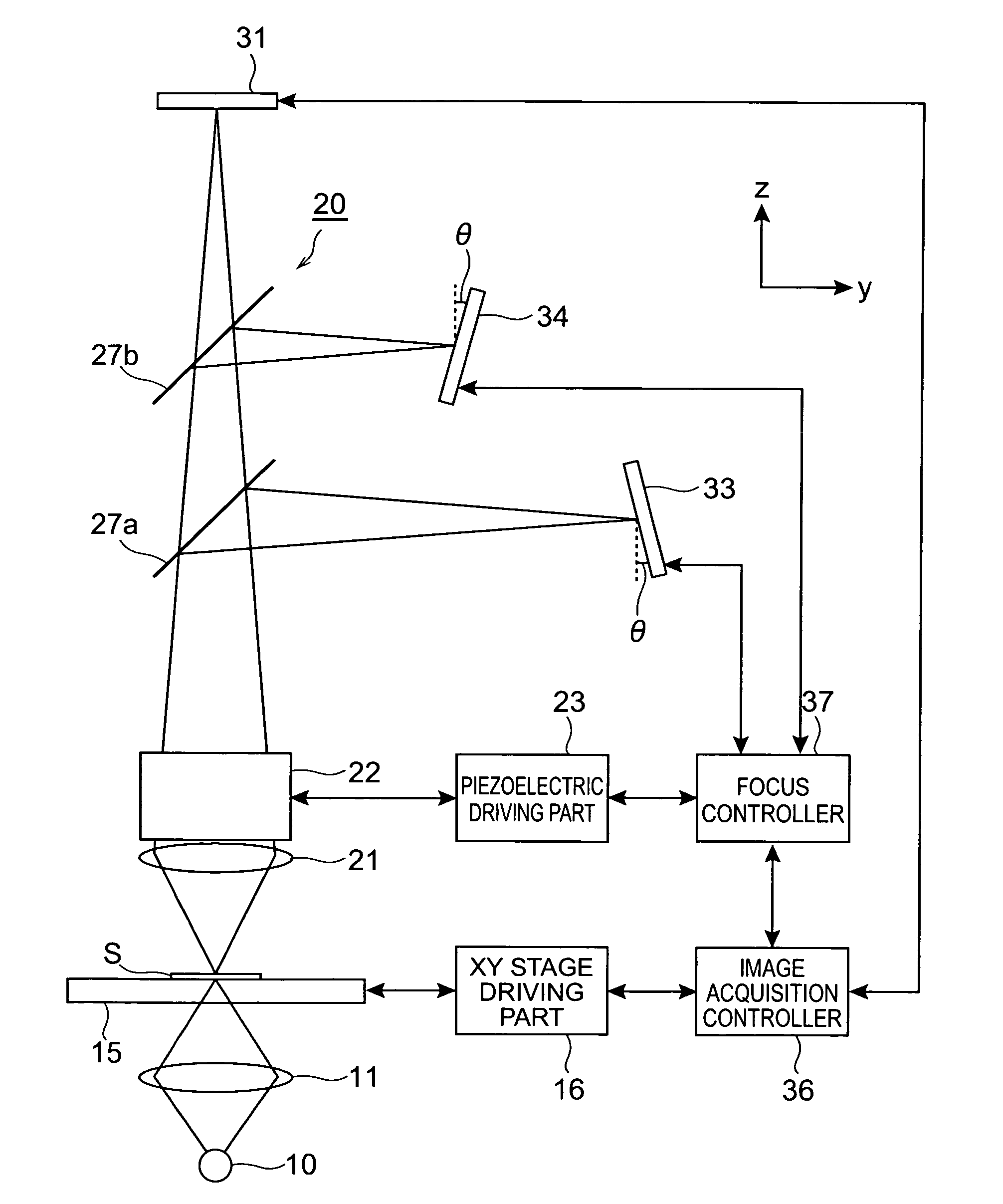
[0053]FIG. 1 is a block diagram showing the construction of a microscope system according to the present invention. The microscope system is designed as a transmission type microscope used to acquire an image of a sample S. The sample S targeted to acquire an image is, for example, a living organism sample, and it is placed on a sample stage 15.

[0054]The sample stage 15 comprises an XY stage movable in the x-direction and y-direction (horizontal directions), and an image pickup position to the sample S is set or changed by driving the XY stage 15 on the xy plane. The sample stage 15 is controlled by an XY stage driving part 16. At the lower side of the sample stage 15 are disposed an irradiation light source 10 for irradiating the sample S with light for generating an optical image which is a target for image pickup and a light converging lens 11 for converging the light from the irradiation light source 10 to the image pickup position set for the sample S.

[0055]A light guiding opti...

second embodiment

[0123]FIG. 15 is a block diagram showing the construction of the microscope system of the present invention. In this embodiment, the irradiation light source 10, the light converging lens 11, the sample stage 15, the XY stage driving part 16, the light guiding optical system 20, the piezoelectric actuator 22 and the piezoelectric driving part 23 are the same as those of the embodiment shown in FIG. 1.

[0124]A photodetector 41 is disposed on the image acquisition optical path at a position corresponding to the image forming plane of an optical image of the sample S which passes through the beam splitters 27a and 27b. The photodetector 41 serves as image acquisition image pickup means used to acquire an image based on the optical image split to the image acquisition optical path by the beam splitters 27a and 27b. As the photodetector 41, specifically a linear sensor for acquiring a one-dimensional image of the sample S or an image sensor which can acquire a two-dimensional image may be...

third embodiment

[0150]FIG. 17 is a block diagram showing the construction of the microscope system of the present invention. In this embodiment, the irradiation light source 10, the light converging lens 11, the sample stage 15 and the XY stage driving part 16 are constructed in the same structure as shown in FIG. 1.

[0151]The light guiding optical system 20 is equipped at the upper side of the sample stage 15 with respect to the sample S. In this embodiment, the light guiding optical system 20 has an objective lens 21 and image forming lens 28 disposed at the rear stage of the objective lens 21. In FIG. 17, an optical path along which light from the objective lens 21 is passed through the image forming lens 28 and an image of the light is formed is commonly used as an image acquisition optical path used for acquiring images of the sample S and a focus control optical path used to carry out focus control when the image of the sample S is picked up.

[0152]The objective lens 21 is provided with a piezo...


PUM


Abstract

A microscope system is constructed by a light guiding optical system 20 having an objective lens 21 and beam splitters 27a and 27b for splitting an optical image of a sample S, a photodetector 31 for acquiring an image of the sample S, and two CCD cameras 33 and 34 for focus control disposed on optical paths split by the beam splitters 27a and 27b. The cameras 33 and 34 are disposed being inclined with respect to the optical path so that the optical paths thereof in the light guiding optical system 20 vary along a z-axis direction in opposite directions to each other. Images acquired by these cameras 33 and 34 are analyzed in a focus controller 37, and the image pickup focal point to the sample S is controlled on the basis of the analysis result, whereby the focus control when an image of the sample is acquired can be suitably performed.

Description

BACKGROUND OF THE INVENTION[0001]1. Field of the Invention[0002]The present invention relates to a microscope system used for acquiring an image of a sample.[0003]2. Related Background of the Invention[0004]When an image of a sample is acquired by using a microscope, a problem of deviation of the focal point occurs due to inclination of an optical system or a mechanism system in the apparatus, inclination or uneven shape of the sample itself, or the like. Under such a situation, it has been hitherto general in a conventional microscope system to carry out automatic focusing (auto-focus) for controlling the focal point of image pickup of an image pickup device such as a CCD camera or the like. As the device for carrying out automatic focusing as described above are known devices described in, for example, Document 1: Japanese Patent Publication No. 3390106, Document 2: Japanese Patent Application Laid-Open No. Hei-09-230250, Document 3: Japanese Patent Application Laid-Open No. Hei-0...

Claims


Application Information

Patent Timeline
Patent Type & Authority Patents(United States)
IPC IPC(8): H04K1/00G02B7/28G02B7/36G02B21/24
CPCG02B21/244G02B21/245
Inventor OSHIRO, MASAFUMIICHIE, KOJI
Owner HAMAMATSU PHOTONICS KK
Why Eureka
Try Eureka