
Optical fiber fabrication

a technology of optical fibers and bundles, applied in semiconductor lasers, manufacturing tools, instruments, etc., can solve the problems of difficult coupling between devices and light sources, laborious and expensive manufacture, and degrading the beam quality produced by devices, so as to reduce the variation in the core size of the structure, the effect of reducing the beam quality of fiber lasers and amplifiers

Active Publication Date: 2010-10-12
LIEKKI OY
View PDF30 Cites 4 Cited by
  • Summary
  • Abstract
  • Description
  • Claims
  • Application Information

AI Technical Summary

Benefits of technology

"The invention provides a solution for manufacturing optical devices such as fiber lasers, couplers, and amplifiers in a more efficient and cost-effective way. The invention allows for the tapering and stretching of optical fibers without inducing core size variations and degrading beam quality. The invention also allows for the integration of pump light into the fiber in a distributed pumping architecture, which simplifies the manufacturing process and reduces the size of the devices. The invention further provides a simplified and economic way to manufacture both the optical fiber and its coupling means, reducing labor and material costs. The invention also allows for the use of multiple discrete fiber couplers and the pumping of fiber lasers from a single point with high power. The invention provides a new type of bundle that allows for optical coupling and distributed pumping without the need for separate pumping points or signal splices. The invention also provides a new type of bundle that allows for the tapering and stretching of optical fibers without inducing core size variations and degrading beam quality."

Problems solved by technology

This leads to a degradation of the beam quality produced by the devices.
Further, the devices require several manufacturing steps, which make their manufacture laborious and expensive.
Also, the devices are difficult to couple with each other and light sources such as laser diodes, especially if many diodes are used (multiple pumping points are installed along the fiber length).

Method used


Image

  • Optical fiber fabrication
  • Optical fiber fabrication
  • Optical fiber fabrication

Examples


example 1

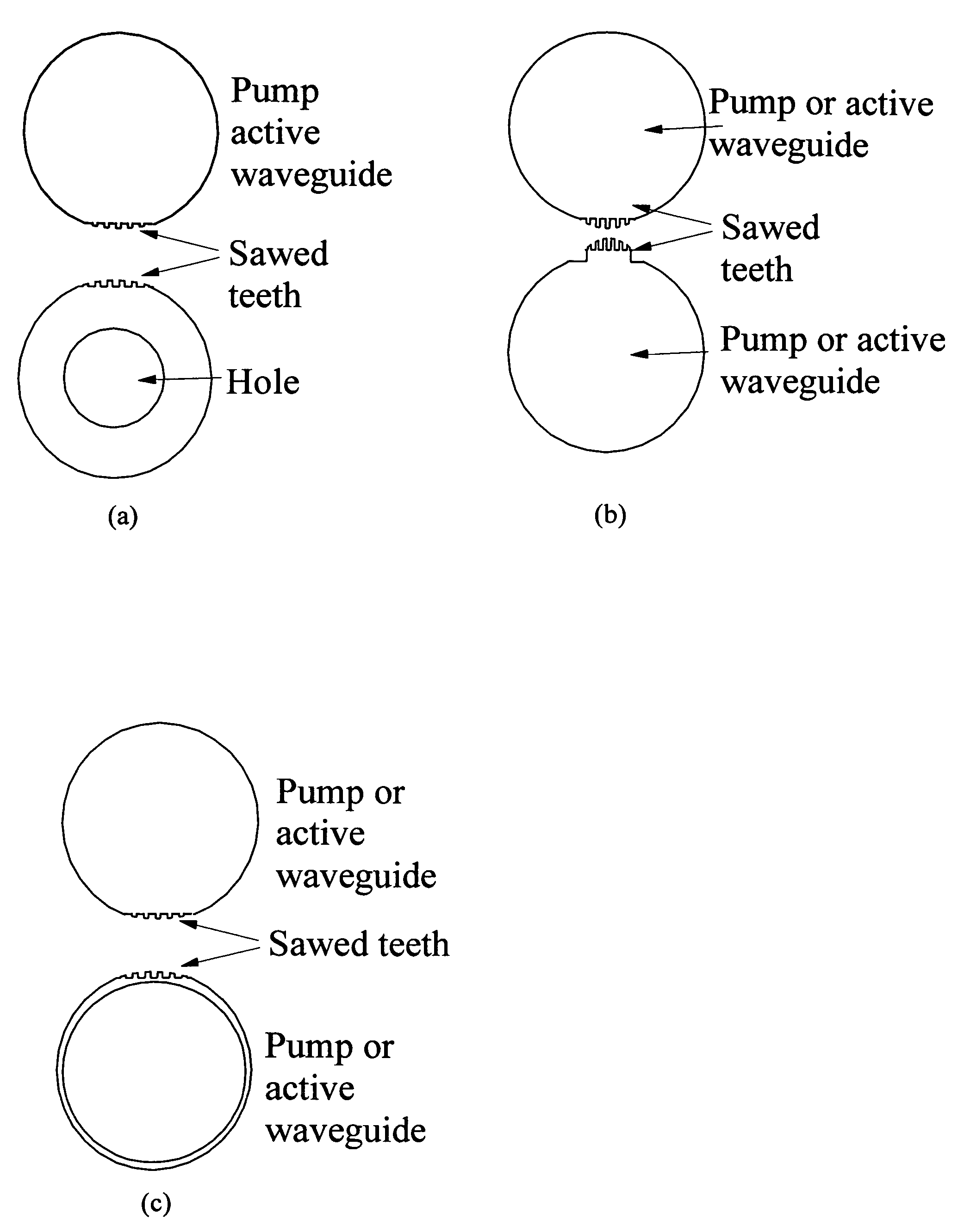
[0074]In one embodiment of the invention, the Key Hole fiber structure (clover fiber) is established, FIG. 5. The fiber structure consists of Pump fiber 10, capillary tube 11 with an air hole 12 in the middle of it, signal fiber 14 with an active core 13, low index polymer coating 15.

example 2

[0075]In a second example, a Key Hole structure type 2 is created, FIG. 6. The fiber structure consists of Pump fiber 10, capillary tube 11 with an air hole 12 in the middle of it, signal fiber 14 with an active core 13, low index polymer coating 15.

example 3

Fiber with Forced Bending Direction

[0076]The compound fiber of the present invention allows for a number of different configurations as far as the size, shape, number and positions of the each of its elements are concerned. Some of these configurations can be used to enhance the properties of the fiber lasers or amplifiers built from such fibers. For instance, it is evident that the fiber geometry of FIG. 7 makes the bending of the fiber to be very difficult along one direction and very easy along the perpendicular direction. This property can be utilized in situations where the direction of fiber bending is important for controlling the modal properties of the active fiber. Thus, the active fiber geometry and orientation with respect to the other elements can be fixed already in the preform manufacturing stage and the spatial relationships will remain the same during and after the fiber drawing process. This property of the fiber of the present invention is of utmost importance esp...


PUM

PropertyMeasurementUnit
diameteraaaaaaaaaa
diameteraaaaaaaaaa
temperatureaaaaaaaaaa

Abstract

The invention relates to a bundle of optical fibers and a process for its preparation, wherein at least two of the optical fibers are at least partly attached to each other lengthwise by means of a removable longitudinal bridging element. Typically, the bridging element is an open one-hole capillary.

Description

FIELD OF THE INVENTION[0001]The present invention relates to a bundle containing optical fibers and to a process for preparing such a bundle. Bundles containing optical devices are useful in fiber lasers and amplifiers, in particular when coupling light from multimode pump sources to one or more double cladding fibers including an active element in the fiber core.BACKGROUND ART[0002]The output powers from double-clad fiber lasers have recently increased tremendously. In recent experiments, hundreds of watts have been achieved from essentially single-mode devices making fiber lasers serious contenders for e.g. lamp and diode pumped (Nd:Glass) Nd:YAG in material processing. Apart from continuous wave operation, pulsed operation and pulse amplification with down to femtosecond range pulses and peak powers well in excess of 100 kW have also been demonstrated with fiber lasers.[0003]Fiber lasers based on double-clad fibers offer several benefits over solid state lasers. The main performa...

Claims


Application Information

Patent Timeline
Patent Type & Authority Patents(United States)
IPC IPC(8): G02B6/04G02BG02B6/28H01S3/094
CPCG02B6/2826H01S3/094003G02B6/04H01S3/094007H01S5/2036
Inventor TAMMELA, SIMOYLA-JARKKO, KALLE
Owner LIEKKI OY
Learn More