
Instantaneous steam boiler

a technology of instantaneous steam and steam boiler, which is applied in the direction of liquid transfer devices, lighting and heating apparatus, container discharge methods, etc., can solve the problems of inability to maintain water, the inability to remove etc., to reduce the length of the heater, suppress the formation of fur or oxidation coating, and increase the contact efficiency between the tube and the heater

Inactive Publication Date: 2010-10-12
HAAN
View PDF9 Cites 32 Cited by
  • Summary
  • Abstract
  • Description
  • Claims
  • Application Information

AI Technical Summary

Benefits of technology

"The present invention provides an instantaneous steam boiler with a U-shaped heater that is curved and twisted, which reduces the length of the heater and makes the entire boiler smaller and lighter. The flow tube is designed to come in contact with the heater, reducing the transfer path and minimizing the formation of fur or oxidation coating. The U-shaped transfer tube increases the contact efficiency between the tube and the heater, making the boiler easy to install in a small space. The invention allows for stable steam supply even when the flow tube length is reduced."

Problems solved by technology

When the transfer tube has an extended length, it is more likely to retain water therein and fur exposure is inevitable.
Unfortunately though, this descaled fur or oxidation coating is particularly fatal to the instantaneous steam boiler.
Because a steam outlet of a conventional instantaneous steam boiler normally has a small volume and a very small diameter, the boiler may easily get clogged up, producing steam in an unstable and non-uniform manner and losing pump pressure.
These drawbacks are led to a serious deterioration in the durability of the steam boiler.

Method used


Image

  • Instantaneous steam boiler
  • Instantaneous steam boiler
  • Instantaneous steam boiler

Examples


embodiment i

[0026]FIG. 3 is a perspective view of an instantaneous steam boiler having a heater and a flow tube arranged 180 degrees apart, facing opposite directions, in accordance with a first preferred embodiment of the present invention. Referring to FIG. 3, a steam boiler 100 according to a first embodiment of the present invention is constituted by a U-shaped heater 110, a U-shaped flow tube 130, and a body 150 for housing said heater 110 and said flow tube 130. Because the flow tube 130 is a separate tube which is formed and then embedded in the body 150, a molding process of the body for forming a complicated flow path within said body is much simplified, compared with conventional techniques for forming a flow path.

[0027]The heater 110 is preferably formed into a U shape. That is, the heater 110 is composed of a first linear portion 111 and a second linear portion 113 in parallel to each other and an arc-shaped return portion 115. Ports 112 and 114 are formed at the other ends of the f...

embodiment ii

[0034]FIG. 4 is a perspective view of an instantaneous steam boiler in accordance with a second preferred embodiment of the present invention. As shown in FIG. 2, although similar in structure and functions, a steam boiler 200 of the second embodiment differs from the steam boiler 100 of the first embodiment by an orthogonal arrangement of a flow tube 230 with respect to a heater 110. By placing the flow tube 230 at right angles to the heater 110, it becomes possible to adjust the gap between a water inlet 231 and a steam outlet 233 of the flow tube 230, thereby expanding the limit of the layout area for product design.

embodiment iii

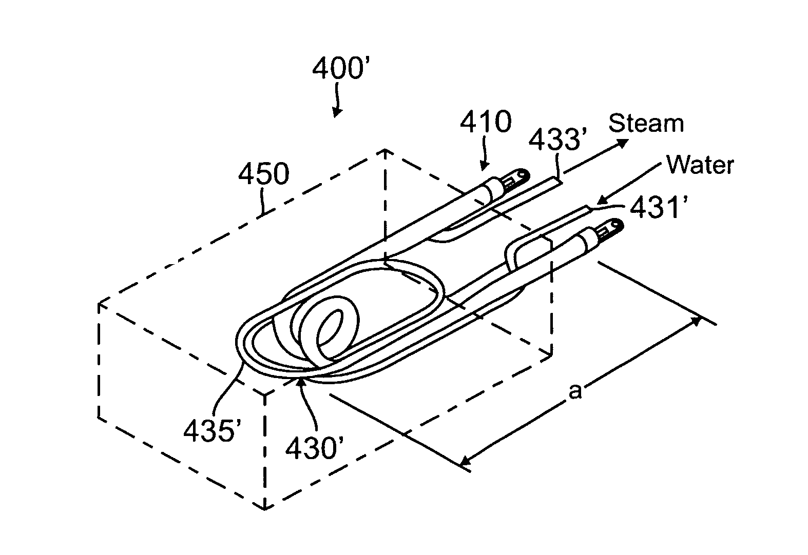
[0035]FIG. 5 is a perspective view of an instantaneous steam boiler in accordance with a third preferred embodiment of the present invention. As shown in FIG. 3, although similar in structure and functions, a steam boiler 300 of the third preferred embodiment differs from the first and second embodiments in that said flow tube 330 is shaped in a coiled form, with a heater 110 arranged orthogonally inside the coil, such that the flow tube 300 is coiled about the heater.


PUM


Abstract

The present invention relates to an instantaneous steam boiler generating steam in a steam cleaner, a steam-vacuum cleaner, a steam iron, etc. The instantaneous steam boiler includes a U-shaped heater and a separate flow tube arranged in parallel and contact with said heater. The flow tube may be arranged orthogonally or at a 180 degree opposite direction and may include a circular or square-shaped end with rounded edges, thereby increasing the heating / vaporization efficiency of the device.

Description

CROSS-REFERENCE(S) TO RELATED APPLICATIONS[0001]1. Related Applications[0002]The present invention claims priority from Korean patent application number 10-2006-0126835, filed on Dec. 13, 2006, which is also hereby incorporated by reference in its entirety.[0003]2. Field of the Invention[0004]The present invention relates to an instantaneous steam boiler generating steam in a steam cleaner, a steam-vacuum cleaner, a steam iron, etc. More specifically, the present invention relates to an instantaneous steam boiler featuring a short heater return line by curving or twisting a U-shaped heater return portion.[0005]3. Background of the Invention[0006]Steam boilers are largely classified into reservoir type water heaters and instantaneous water heaters. The reservoir type water heater has an electric boiler built in a water tank. By heating the steam boiler, water temperature increases and the heated water finally generates steam (vapor). The steam is then discharged through a steam outle...

Claims


Application Information

Patent Timeline
Patent Type & Authority Patents(United States)
IPC IPC(8): F24H1/18
CPCF22B1/288B08B2230/01F24H1/142F24H9/1818F24H2250/02
Inventor HAAN, GYUNG-HEE
Owner HAAN
Learn More