
Shared-memory switch fabric architecture

a fabric architecture and memory switch technology, applied in data switching networks, instruments, digital transmission, etc., can solve the problems of overworked memory in active ports and idle ports, and achieve the effect of modest maximum memory speed, convenient stripping of each data segment, and high port coun

Active Publication Date: 2010-10-12
TAHOE RES LTD
View PDF51 Cites 16 Cited by
  • Summary
  • Abstract
  • Description
  • Claims
  • Application Information

AI Technical Summary

Benefits of technology

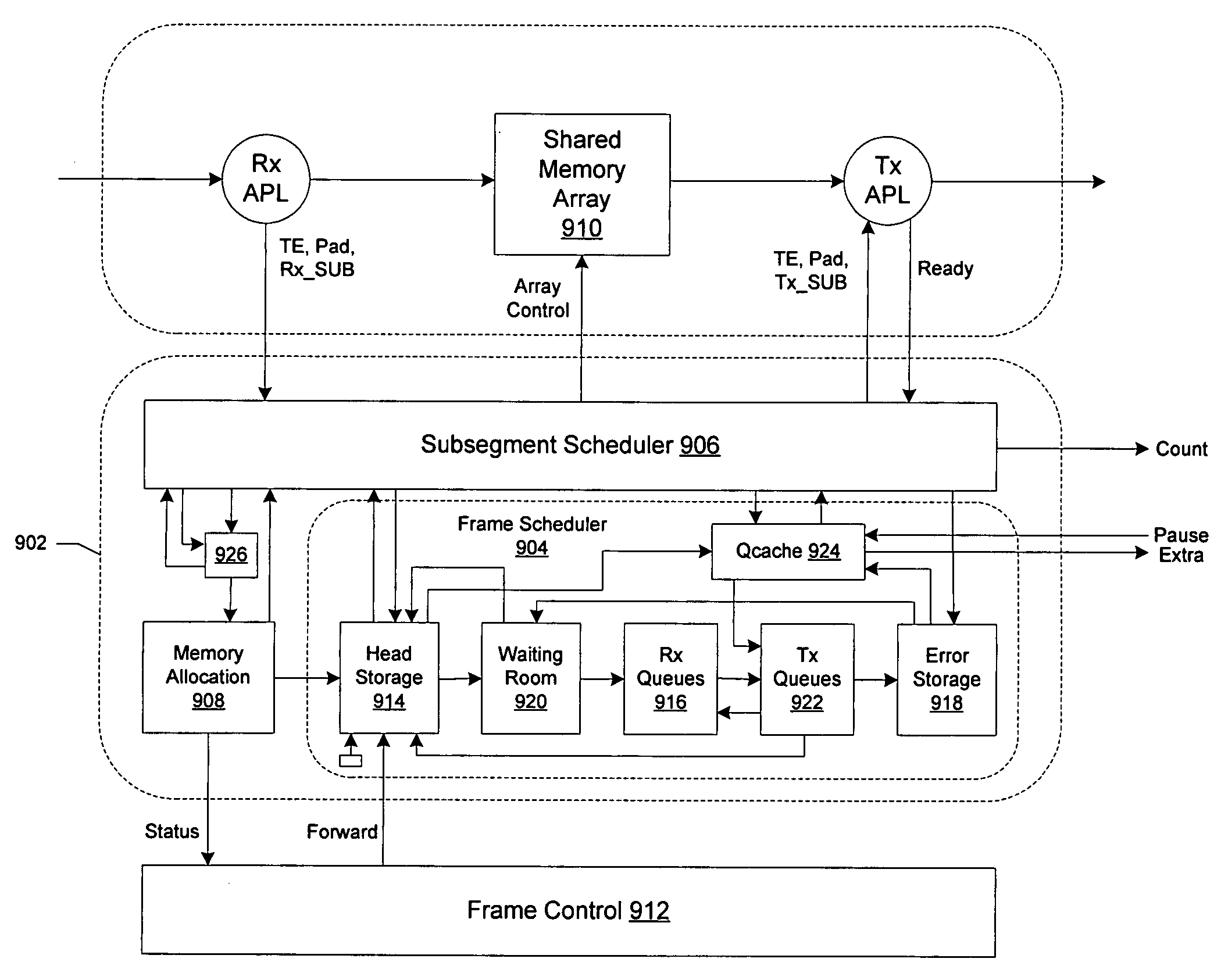
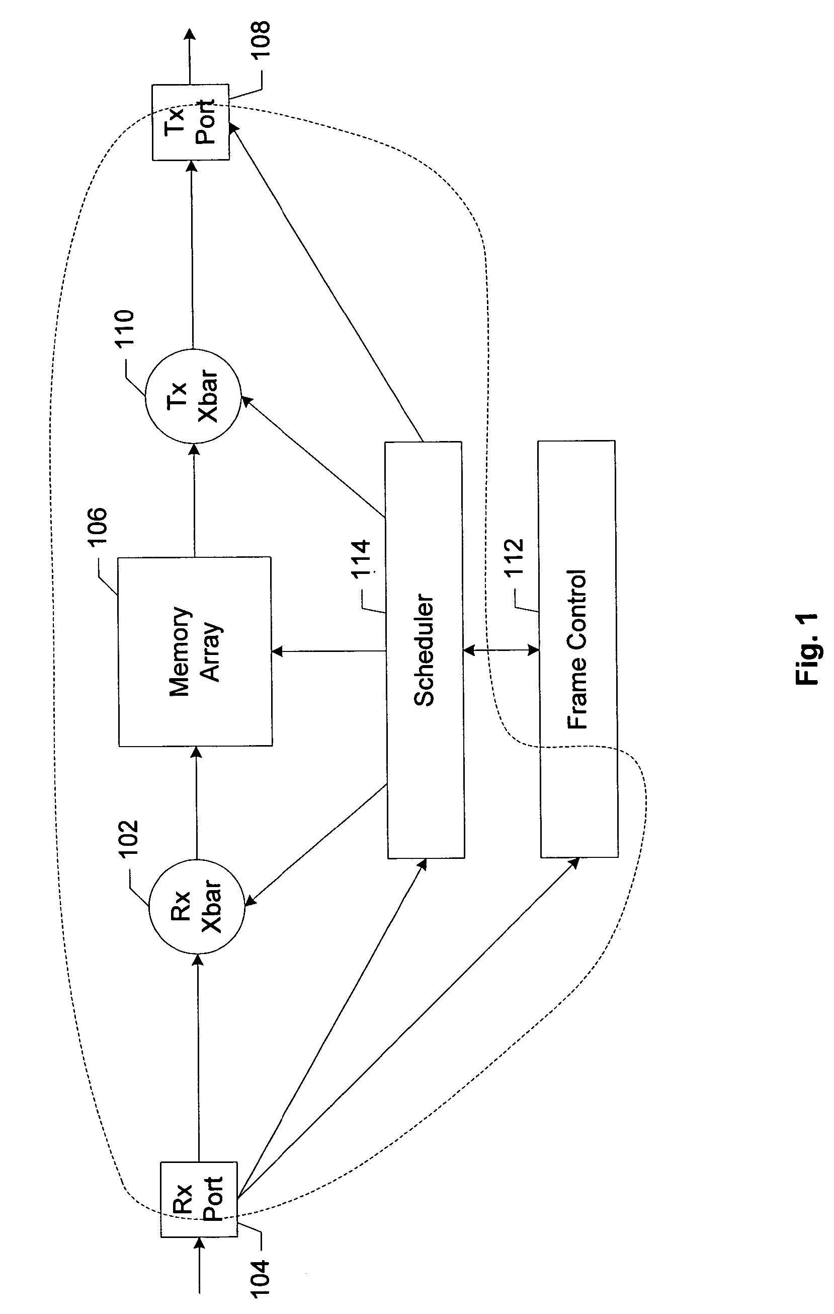
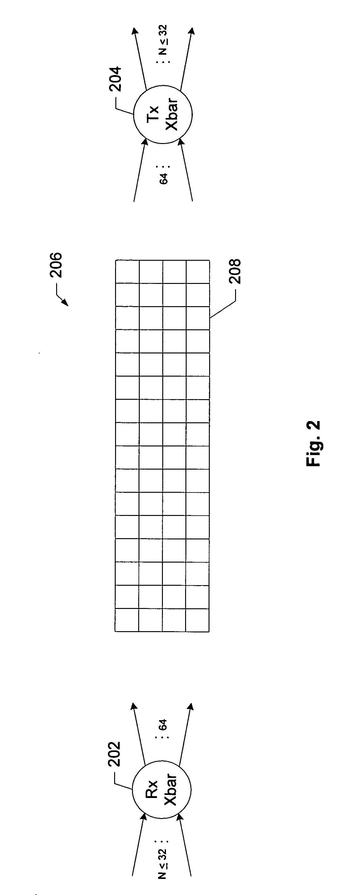
The present invention provides a shared memory architecture that allows for a high number of ports while maintaining a modest maximum memory speed. The architecture includes a shared memory with multiple receive and transmit ports, organized in rows and columns. Non-blocking circuitry is used to connect any port with any memory bank. Scheduling circuitry controls the interaction of the ports, crossbar circuitry, and memory array to facilitate storage and retrieval of data segments. The scheduling circuitry also allows for striping of data segments across the memory banks and rows. Overall, the invention provides a more efficient and effective shared memory architecture for high-speed data processing.

Problems solved by technology

That is, if the memory resides in the ports themselves, the memory in idle ports sits unused while the memory in active ports may be overworked, particularly where the transmission protocol allows very large packets.
Conventional approaches to designing such architectures employ synchronous circuits and design flows which face significant obstacles, particularly as both the number of ports and the required speed of each port continue to increase.

Method used


Image

  • Shared-memory switch fabric architecture
  • Shared-memory switch fabric architecture
  • Shared-memory switch fabric architecture

Examples


Embodiment Construction

[0016]Reference will now be made in detail to specific embodiments of the invention including the best modes contemplated by the inventors for carrying out the invention. Examples of these specific embodiments are illustrated in the accompanying drawings. While the invention is described in conjunction with these specific embodiments, it will be understood that it is not intended to limit the invention to the described embodiments. On the contrary, it is intended to cover alternatives, modifications, and equivalents as may be included within the spirit and scope of the invention as defined by the appended claims. In the following description, specific details are set forth in order to provide a thorough understanding of the present invention. The present invention may be practiced without some or all of these specific details. In addition, well known features may not have been described in detail to avoid unnecessarily obscuring the invention.

[0017]Various embodiments will be descri...


PUM


Abstract

A shared memory is described having a plurality of receive ports and a plurality of transmit ports characterized by a first data rate. A memory includes a plurality of memory banks organized in rows and columns. Operation of the memory array is characterized by a second data rate. Non-blocking receive crossbar circuitry is operable to connect any of the receive ports with any of the memory banks. Non-blocking transmit crossbar circuitry is operable to connect any of the memory banks with any of the transmit ports. Buffering is operable to decouple operation of the receive and transmit ports at the first data rate from operation of the memory array at the second data rate. Scheduling circuitry is operable to control interaction of the ports, crossbar circuitry, and memory array to effect storage and retrieval of the data segments in the shared memory. The scheduling circuitry is further operable to facilitate striping of each data segment of a frame across the memory banks in one of the rows, and to facilitate striping of successive data segments of the frame across successive rows in the array.

Description

RELATED APPLICATION DATA[0001]The present application claims priority under 35 U.S.C. 119(e) to U.S. Provisional Patent Application No. 60 / 643,794 filed on Jan. 12, 2005 (FULCP011P), the entire disclosure of which is incorporated herein by reference for all purposes.BACKGROUND OF THE INVENTION[0002]The present invention relates to a switch fabric architecture. More specifically, the present invention provides a shared memory switch architecture which may be employed to switch frames or packets of arbitrary lengths between any of its ports with sustained high speed throughputs.[0003]Shared memory architectures are advantageous for high speed switches with many ports because they make more efficient use of memory. That is, if the memory resides in the ports themselves, the memory in idle ports sits unused while the memory in active ports may be overworked, particularly where the transmission protocol allows very large packets. In addition, where the transmission protocol for which the...

Claims


Application Information

Patent Timeline
Patent Type & Authority Patents(United States)
IPC IPC(8): G06F12/00
CPCG11C7/1048G11C7/1075H04L49/103H04L49/101H04L49/351
Inventor CUMMINGS, URILINES, ANDREWPELLETIER, PATRICKSOUTHWORTH, ROBERT
Owner TAHOE RES LTD
Learn More